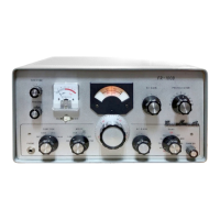
CONTROLS
AND
SWITCHES
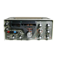
The FR-101 has been specifically designed for ease
of
operation and versatility.
All
controls have been pro-
perly adjusted at
the
factory. Several panel controls and
switches are unusual in operation, and improper adjust-
ment may result in poor receiver performance. The
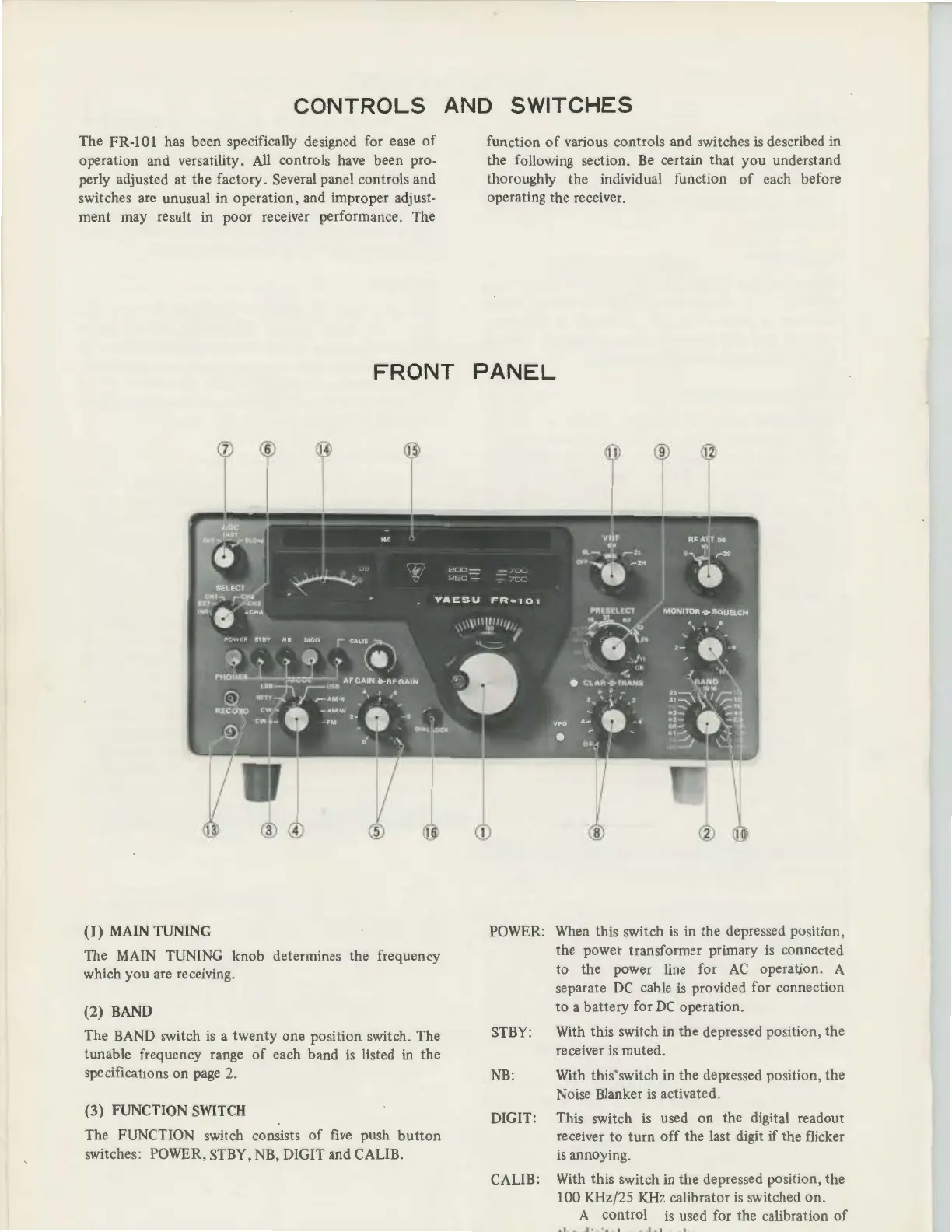
FRONT
(1)
MAIN
TUNING
The MAIN TUNING knob determines the frequency
which
you
are receiving.
(2)
BAND
The BAND switch
is
a
twenty
one position switch. The
tunable frequency range
of
each band
is
listed in the
spe:::ifications on page 2.
(3)
FUNCTION
SWITCH
The FUNCTION switch consists
of
five push
button
switches: POWER, STBY,
NB
, DIGIT and CALIB.
function
of
various controls and switches
is
described
in
the following section.
Be
certain
that
you understand
thoroughly the individual function
of
each before
operating the receiver.
PANEL
POWER: When this switch
is
in the depressed position,
the power transformer primary
is
connected
to
the power line for
AC
operation. A
separate
DC
cable
is
provided for connection
to
a battery for
DC
operation.
STBY: With this switch in the depressed position, the
receiver
is
muted.
NB
: With this switch in the depressed position, the
Noise Blanker
is
activated.
DIGIT: This switch
is
used
on
the digital readout
receiver
to
turn
off
the last digit
if
the flicker
is
annoying.
CALIB: With this switch in the depressed position, the
100 KHz/25 KHz calibrator
is
switched on.
A control is used for the calibration
of
-LL - .J
:_:.,._
1
--
-
.l.
1
-·
- '
-·


 To Next Page