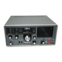
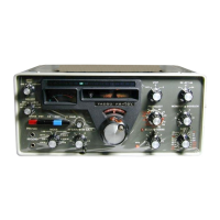
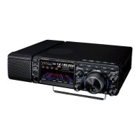
The FRG-7 Digital is a modification designed to enhance the Yaesu FRG-7 communications receiver, a device originally produced in the late 1970s and early 1980s. The primary function of this modification is to replace the original analog frequency readout and S-meter with a modern digital display, while maintaining the receiver's core functionality and minimizing mechanical interventions. The modification is based on an Arduino Nano microcontroller.
Function Description:
The FRG-7 Digital provides a high-contrast color TFT screen that displays the current frequency and a digital S-meter. It aims to offer a more precise and readable frequency readout compared to the original analog scale, which was based on the Wadley Loop principle. The digital S-meter incorporates the AGC (Automatic Gain Control) characteristic of the FRG-7, providing S-meter values that correspond accurately to the antenna input voltages. A key feature is the ability to account for frequency shifts when switching between AM, LSB (Lower Sideband), and USB (Upper Sideband modes, offering an optional offset adjustment for each mode to ensure correct frequency indication. This is particularly useful as the original analog scale could have slight deviations and non-linear frequency progression. The modification is designed to be reversible, allowing the receiver to be returned to its original state if desired.
Important Technical Specifications:
- Frequency Range: The Yaesu FRG-7 receiver operates from 500 kHz to 29.99 MHz. The FRG-7 Digital modification works within this range.
- Microcontroller: Arduino Nano.
- Display: 1.14-inch TFT display, chosen for its high contrast and readability.
- Power Supply: The readout utilizes the existing 10.6V power supply from the FRG-7's IF-AF unit (TP408).
- VFO Signal Input: The VFO signal for frequency counting is taken from test point TP404 on the IF-AF unit, requiring a shielded cable for connection due to its high-frequency nature.
- S-meter Input: The digital S-meter receives its signal from the original S-meter's connection points (J2 for signal, J3 for ground) on the PCB.
- Mode Detection: For LSB and USB offset functionality, the system detects the selected mode via a free position on the MODE switch S2, connecting to J8 (LSB) and J9 (USB) on the PCB.
- Calibration: The frequency counter includes a calibration routine to compensate for slight variations in the Arduino Nano's crystal frequency. This calibration is pre-set in factory-prepared units and stored in EEPROM.
- Offsets: Adjustable offsets for AM, LSB, and USB modes are stored in EEPROM.
Usage Features:
- Digital Frequency Readout: Replaces the analog drum, offering precise frequency display for AM, LSB, and USB.
- Digital S-meter: Integrated into the TFT display, providing an accurate indication of signal strength, calibrated to the FRG-7's AGC characteristics.
- Display Brightness Adjustment: A jumper (J7) allows selection between bright and dim display modes, with the chosen setting stored in EEPROM.
- AM Offset Adjustment: Allows users to compensate for slight deviations in the FRG-7's IF frequency, ensuring the VFO frequency aligns with the center of the IF filter for AM stations. This setting is crucial for accurate LSB/USB indication.
- SSB Offset Adjustment (LSB/USB): Separate procedures for LSB and USB allow users to set offsets to achieve "zero beat" on broadcast stations, ensuring correct frequency display in SSB modes. This feature requires the MODE switch to be wired to the PCB.
- Offset Removal: A procedure is available to reset all AM, LSB, and USB offset values to zero, effectively disabling mode indication if no offsets are programmed.
- Counter Calibration: While pre-calibrated, a routine is available for users with accurate signal generators to recalibrate the frequency counter, ensuring high accuracy. This setting is stored in EEPROM.
- Minimal Mechanical Intervention: The design aims to use existing mounting points and minimize permanent changes to the receiver's chassis.
Maintenance Features:
- Reversibility: The modification is designed to be easily undone, allowing the FRG-7 to be restored to its original analog configuration.
- S-meter Replacement (Optional): If the original S-meter is completely removed, it must be replaced with a 640 Ohm resistor (e.g., 560 Ohm and 82 Ohm in series) soldered over J2 and J3 to maintain circuit integrity.
- EEPROM Storage: All user-defined settings, including display brightness, AM, LSB, and USB offsets, and calibration values, are stored in the EEPROM, ensuring they persist even after power cycling.
- Warm-up Requirement for SSB Offset: Before adjusting SSB offsets, the FRG-7 must be warmed up for at least half an hour to ensure the BFO (Beat Frequency Oscillator) is stable, as it is known to be less stable when cold.
- Jumper Usage: Specific jumpers (J6, J7) are used for configuration and calibration. It is critical to follow the instructions for placing and removing these jumpers to avoid unwanted situations or incorrect settings.
- Shielded Cabling: The VFO signal connection requires a shielded audio cable to prevent interference, with the shielding connected to a ground point (TP402).
- Clear Wiring Instructions: The manual provides detailed steps for connecting power, VFO signal, S-meter, and mode selection wires, including specific test points and PCB connectors.