FT2DR/DE Technical Supplement
Alignment
ALIGNMENT-3
A-Band 430 MHz Band Adjustment
Receiver Sensitivity Adjustment (TUNE DEV)
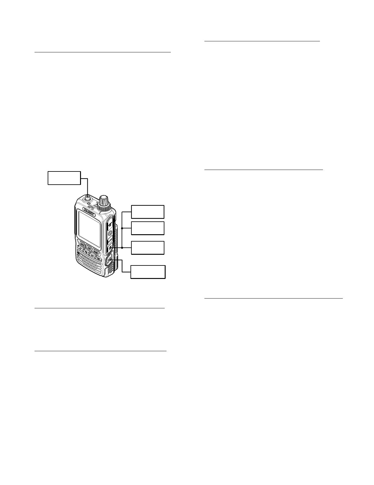
Connect the test equipment as shown in Figure 2:
RX Alignment Setup.
Rotate the
DIAL
knob to select the Alignment
Menu "TUNE DEV".
Set the RF Signal Generator output to 435.100
MHz, at a level of -10.0 dBμ, ±3.5 kHz deviation
with a 1 kHz audio tone.
Press the
[
V/M
]
button (the "Data" will appear
on the display).
Rotate the
DIAL
knob for maximum deection
on the SINAD meter.
Press the
[
V/M
]
button (the "Data" will disap-
pear on the display).
Figure 2: RX Alignment Setup
Squelch Hysteresis Conrmation (HIS SQL)
Rotate the
DIAL
knob to select the Alignment
Menu "HIS SQL".
Conrm that the alignment value is "0".
Squelch Threshold Adjustment (THLD SQL)
Connect the test equipment as shown in Figure 2:
RX Alignment Setup.
Rotate the
DIAL
knob to select the Alignment
Menu "THLD SQL".
Set the RF Signal Generator output to 435.100
MHz, at a level of -12 dBμ, ±3.5 kHz deviation
with a 1 kHz audio tone.
Press the
[
V/M
]
button (the "Data" will appear
on the display).
Press the
[
X
]
key two times to store the Squelch
Threshold level
Press the
[
V/M
]
button (the "Data" will disap-
pear on the display).
Tight Squelch Adjustment (TIGH SQL)
Connect the test equipment as shown in Figure 2:
RX Alignment Setup.
Rotate the
DIAL
knob to select the Alignment
Menu "TIGH SQL".
Set the RF Signal Generator output to 435.100
MHz, at a level of -4 dBμ, ±3.5 kHz deviation
with a 1 kHz audio tone.
Press the
[
V/M
]
button (the "Data" will appear
on the display).
Press the
[
X
]
key two times to store the Squelch
Tight level.
Press the
[
V/M
]
button (the "Data" will disap-
pear on the display).
FM S-Meter S-1 Adjustment (S1 LEVEL)
Connect the test equipment as shown in Figure 2:
RX Alignment Setup.
Rotate the
DIAL
knob to select the Alignment
Menu "S1 LEVEL".
Set the RF Signal Generator output to 435.100
MHz, at a level of -7 dBμ, ±3.5 kHz deviation
with a 1 kHz audio tone.
Press the
[
V/M
]
button (the "Data" will appear
on the display).
Press the
[
X
]
key two times to store the FM
S-Meter S-1 level.
Press the
[
V/M
]
button (the "Data" will disap-
pear on the display).
FM S-Meter Full-Scale Adjustment (S9 LEVEL)
Connect the test equipment as shown in Figure 2:
RX Alignment Setup.
Rotate the
DIAL
knob to select the Alignment
Menu "S9 LEVEL".
Set the RF Signal Generator output to 435.100
MHz, at a level of +20 dBμ, ±3.5 kHz deviation
with a 1 kHz audio tone.
Press the
[
V/M
]
button (the "Data" will appear
on the display).
Press the
[
X
]
key two times to store the FM
S-Meter Full Scale level.
Press the
[
V/M
]
button (the "Data" will disap-
pear on the display).
Regulated
9.4 VDC P.S.
SINAD
Meter
8-ohm
AF Load
RF Signal
Generator
AF Generator