10
“Sub” band
A portion of the output from the UHF-VCO/A Q1123
(2SC5006) is passed through buffer amplifier Q1124
(2SC5006) and diode switch D1093 (HVC131) to the pro-
grammable divider section of the PLL IC Q1122
(MB15A02PFV1), where it is divided according to the fre-
quency dividing data associated with the operating fre-
quency input from the main CPU Q1104. It is then sent to
the phase comparator.
A portion of the output from the VHF-VCO/A Q1126
(2SC5374) is passed through buffer amplifier Q1127
(2SC5374) and diode switch D1097 (HVC131) to the pro-
grammable divider section of the PLL IC Q1122, where it
is divided according to the frequency dividing data asso-
ciated with the operating frequency input from the main
CPU Q1104. It is then sent to the phase comparator.
The 11.7 MHz reference oscillator X1003 frequency is di-
vided by the reference frequency divider section of Q1122
into 2340 or 1872 parts to become 5 kHz or 6.25 kHz com-
parative reference frequencies, which are utilized by the
phase comparator.
The phase comparator section of Q1122 compares the
phase between the frequency-divided oscillation frequen-
cy of the VCO circuit and the comparative frequency, and
its output is a pulse corresponding to the phase differ-
ence. This pulse is integrated by the loop filter into a con-
trol voltage (VCV) to control the oscillation frequency of
the VCOs.
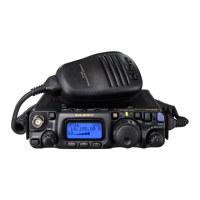
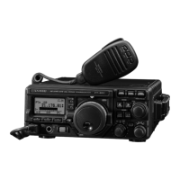
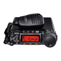
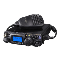
Circuit Description
Power Supply Line
When the user presses and holds in the “Right” VOL knob
for 2 seconds, pin 23 of the main CPU Q1104 goes “low”
and pin 40 of main CPU Q1104 goes “high,” which acti-
vates the power switch Q1078 (2SB1301) and Q1082
(2SC4617), to supply 13.8 VDC to each circuit in the trans-
ceiver.
 Loading...