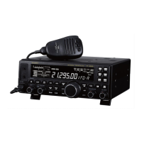
Do you have a question about the Yaesu FT DX 3000 and is the answer not in the manual?
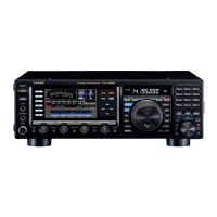
Controls for antenna selection, RF amplification, and noise reduction.
Knobs for adjusting microphone level, CW speed, speech processing, and RF power.
Controls for IF Notch, Contour filter, IF Shift, Bandwidth, and Noise Blanker.
Buttons for accessing the spectrum scope and the main menu system.
Switches for selecting and navigating menu items and settings.
Indicators and switches for VFO-A/VFO-B receive/transmit status.
Switches for memory storage/recall, narrow bandwidth, and split operation.
Switches for split frequency operation and controls for VFO-B tuning.
Connects main antennas, DC power supply, and provides ground terminal.
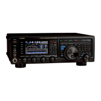
Displays spectrum scope for monitoring band conditions.
Provides methods for efficient frequency tuning and entry.
Explains the receiver front-end circuitry and features.
Provides narrow-band selectivity with selectable IF filters.
Inserts RF attenuation to reduce strong signals or high noise.
Provides ultra-sharp RF selectivity for the transceiver front end.
Optimizes receiver front-end characteristics based on signal strength.
Provides selectable IF filters for improved reception on crowded bands.
Reduces pulse noise caused by automotive ignition systems.
Moves the DSP filter passband to reduce interference.
Varies the width of the DSP IF passband to reduce interference.
Selects a narrow IF DSP filter setting with one-touch operation.
Slices out interfering beat notes or carrier signals from the passband.
Reduces random noise using DSP algorithms for better reception.
Provides manual adjustment of receiver RF and IF stage gain.
Compensates for fading and propagation effects, maintains audio output.
Sets the desired maximum TX power output for SSB mode.
Steps to activate and use the built-in Automatic Antenna Tuner.
Provides precise control over low, mid, and treble audio ranges.
Guide to configuring the microphone equalizer settings.
Increases "talk power" and adjusts audio quality via compression.
Varies transmit bandwidth for different levels of fidelity or talk power.
Utilizes Voice Memory for storing and playing repetitive messages.
Provides hands-free, automatic transmitter activation based on voice input.
Sets transmitter offset frequency for DX "split" operation.
Utilizes VFO-A and VFO-B for flexible split frequency operations.
Sets a one-touch +5 kHz offset for VFO-B transmit frequency.
Connects and configures straight key or emulation devices.
Utilizes the transceiver's integrated electronic keyer.
Enables quick TX/RX switching for hearing signals between dots/dashes.
Ensures precise frequency alignment with incoming CW stations.
Utilizes FH-2 keypad for CW message storage and transmission.
Explains utilization on 29 MHz and 50 MHz repeaters.
Overview of memory storage and recall features.
Allows storage and recall of up to 99 memories with status info.
Scans VFO frequencies and halts on received signals.
Scans programmed memory channels and halts on received signals.
Decodes RTTY signals and displays text on the TFT screen.
Memorizes and transmits RTTY phrases using FH-2 keypad.
Decodes PSK signals and displays text on the AF-FFT screen.
Memorizes and transmits PSK phrases using FH-2 keypad.
Explains how to navigate and adjust transceiver settings via the Menu.
Menu items for transmit audio equalization and speech processor.
General transmitter settings like power, VOX, and emergency freq.
Information on connecting the FC-40 to the transceiver.
Instructs the microprocessor that the FC-40 is being used.
Steps to activate and use the FC-40 Automatic Antenna Tuner.
Provides ultra-sharp RF selectivity for the transceiver front end.
General technical specifications of the transceiver.
Technical specifications related to the transmitter section.
Technical specifications for the receiver section.
| Type | HF/50 MHz Transceiver |
|---|---|
| Antenna Impedance | 50 ohms |
| Frequency Range | 1.8 - 54 MHz |
| Modes | SSB, CW, AM, FM |
| Receiver Type | Triple conversion superheterodyne |
| Audio Output | 2.5 W |
| Supply Voltage | 13.8 V DC ±15% |
| Current Consumption | 22 A |