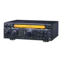
Do you have a question about the Yaesu FT-990 and is the answer not in the manual?
Details on receiving/transmitting frequency ranges, stability, and supply voltage.
Details on transmitter power output, duty cycle, modulation types, and radiation.
Receiver circuit type, IFs, sensitivity, selectivity, and audio output.
List of accessories included with the FT-990, such as power cords and plugs.
Details on SP-6 loudspeaker, headphones, and optional phone patch.
Information on DVS-2 voice system and FIF-232C CAT interface.
Optional IF crystal filters for enhanced CW and SSB selectivity.
Preliminary inspection, power connection, and AC voltage setting.
Recommendations for transceiver location, grounding, and front feet adjustment.
Guidance on antenna connection, SWR, and interconnecting accessories.
Details on the internal memory backup switch and battery.
Pinout details for RTTY, Packet, CAT, and Remote DIN jacks.
Pinouts for Phones, Keyer, External Speaker, and RCA connectors.
Diagrams showing connections for SP-6 and FL-7000.
Details on connecting external linear amplifiers, including T/R switching.
Procedure for removing the top cover and adjusting button beep volume.
Adjusting CW sidetone, keyer settings, and rear panel audio output levels.
Adjusting mode-specific tuning rates and slow AM auto AGC.
Procedure for removing the transceiver's bottom cover for internal access.
Location and adjustment of the AGC Auto Jumper for AM mode.
Description of POWER button, pushbutton switches, and METER selector.
Controls for AGC, speech processor, keyer, MIC, and RF gain.
Functions of tuning knob, LOCK button, and horizontal pushbuttons.
Controls for IF filters, tuner, scan, bandwidth, and keypad.
Controls for memory selection, checking, and CLAR offset tuning.
Controls for RTTY tone, FM deviation, and FM mic gain.
Adjusting VOX gain/delay and setting DIP switches.
Adjusting carrier insertion point and using the backup switch.
Connections for DVS-2, Packet TNC, and RTTY terminal unit.
Connections for AF output, patch input, power, and ground.
Connections for main antenna, EXT ALC, and REMOTE control.
CAT DIN jack for computer control and BAND DATA DIN jack.
Initial setup, control presets, and basic operation of the FT-990.
Techniques and controls for minimizing interference on HF bands.
Using the transmitter, automatic antenna matching, and speech processor.
Storing, checking, recalling, scanning, and blanking memory channels.
Features for AMTOR, RTTY, and Packet digital modes.
Using the CAT system for computer control and command structure.
Data returned by Update, Read Flags, and Read Meter commands.
Table of CAT command opcodes, parameters, and descriptions.
Details on update data structure, 16-byte records, and flags.
Procedure for installing the optional TCXO-2 high-stability oscillator.
Installation of optional IF filters for enhanced selectivity.
Connecting the transceiver for DC operation using an external power source.
Specifics for DC installation in a mobile environment.
| Type | HF Transceiver |
|---|---|
| Frequency Range RX | 0.1-30 MHz |
| Receiver Type | Triple conversion superheterodyne |
| Antenna Impedance | 50 ohms |
| Power Supply | 13.8 VDC |
| Modes | SSB, CW, AM, FM |
| Output Power | 100 W (SSB, CW), 40 W (AM), 25 W (FM) |
| Selectivity | 2.4 kHz (SSB), 500 Hz (CW), 6 kHz (AM), 12 kHz (FM) |


