Do you have a question about the Yaesu FT-991A and is the answer not in the manual?
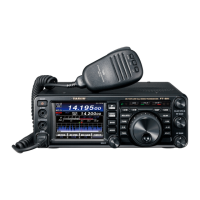
Features a 3.5-inch full-color TFT display showing graphical status of functions like band, noise, and signal reduction.
Supports V/D mode for simultaneous voice/data and Voice FR mode for high-quality digital audio.
Enables group communication via DG-ID and personal communication via DP-ID for C4FM digital mode.
Equipped with 3 kHz and 15 kHz roofing filters for attenuation of out-of-band signals during contests.
Provides two selectable RF amplifiers for optimal receiver gain across HF bands.
Features a 30.225 MHz oscillator with ±0.5 ppm stability for enhanced frequency stability.
Allows optimal wide-to-narrow bandwidth switching and passband shift for interference reduction.
Provides gentle shaping of the DSP passband filter for effective noise control and signal enhancement.
Utilizes 15 algorithms to analyze and suppress ambient noise on HF/50 MHz bands.
Eliminates beat signals with NOTCH and attenuates multiple interfering signals with DNF.
Delivers 100W output for HF/50MHz bands and 50W for 144/430 MHz bands.
Features a three-stage parametric equalizer for precise adjustment of audio spectrum.
Provides visual display of band conditions and signal strength in real time.
Includes a relay switching high-speed digital tuner with 100-channel data memory.
Allows storage and playback of up to 20 seconds of audio for five messages.
Enables one-touch access to any selected Menu item via the C.S button.
Provides critical safety information regarding device operation, electrical hazards, and prohibited actions.
Instructions for setting up the wire stand to tilt the transceiver for optimal viewing.
Procedure to adjust the drag of the Main Tuning Dial knob for user preference.
Step-by-step guide to set the internal clock time and date on the transceiver's LCD.
Procedure for entering the user's call sign on the transceiver for identification.
Instructions for resetting memories, menu settings, or performing a full device reset.
Guidelines for connecting antennas and using 50-ohm coaxial cable for optimal performance.
Importance and methods for establishing an effective ground system for safety and performance.
Proper procedures for connecting antenna coaxial and DC power cables, observing polarity.
Details on connecting external accessories like microphones, headphones, and remote control keypads.
Information on connecting CW keyer paddles or computer-driven keying devices to the KEY jack.
Diagram and instructions for connecting the VL-1000 linear amplifier for enhanced transmission.
Pinout details for various connectors including MIC, GPS/CAT, RTTY/DATA, TUN/LIN, DC IN, and KEY.
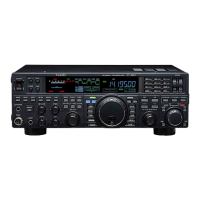
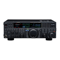
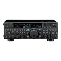
Detailed description of all front panel buttons, knobs, and jacks for operating the transceiver.
Explains various display elements like VFO, S-meter, mode indicators, and main control buttons.
Describes the function of the RX/TX indicators, Memory mode indicators, and FAST/LOCK indicators.
Details the purpose and connection for rear panel jacks like GND, ANT, GPS/CAT, USB, and REM/ALC.
Explains the function of each button on the MH-31A8J microphone, including PTT and scan buttons.
Details the functions of the FH-2 keypad for voice memory and contest memory keyer control.
Describes the DTMF function and keypad illumination features of the MH-36E8J microphone.
Guides on powering up, setting frequency and mode, and adjusting AF GAIN for normal reception.
Details on accessing and using the pre-programmed memory channels for the 60-meter band.
Explains how to use the CLAR button and knob to offset receive/transmit frequencies.
How to lock the Main Tuning Dial knob to prevent accidental frequency changes.
Adjusting the illumination level of the TFT display and LED indicators via menu settings.
Customizing the background color of the VFO-A frequency display on the TFT.
Utilizing triple band-stack VFO technique for storing and recalling up to three favorite frequencies/modes.
Programming the front panel C.S button for direct access to frequently used Menu Mode selections.
Automatic selection of C4FM/FM modes based on received signal, with manual TX mode lock.
Describes receiver features like Contour, IF Shift, IF Width, IF Notch, DNR, and AGC.
Sweeps the spectrum scope once to display band conditions.
Continuously sweeps the spectrum scope for real-time band monitoring.
Directly entering frequencies using the on-screen keyboard via the BAND button.
Adjusting frequency steps using the MULTI knob after selecting CH DIAL function.
Scanning frequencies upward or downward using the microphone's UP/DWN buttons.
Activating the attenuator to reduce strong signals or high noise levels on low frequency bands.
Optimizes receiver front-end characteristics for noise level and signal strength.
Reduces noise caused by automotive ignition systems and other pulse noise sources.
Adjusts passband filter segments to suppress or boost frequency components for clarity.
Moves the DSP filter passband to reduce or eliminate interference without retuning.
Varies the DSP IF passband width to reduce interference or enhance signal fidelity.
Combines IF SHIFT and WIDTH features for effective interference-fighting filtering.
Enables one-touch selection of narrow IF DSP filter settings for quick interference reduction.
Cuts out interfering beat notes or carrier signals from inside the receiver passband.
An Auto-Notch feature that nulls interfering beat notes within the receiver passband.
Reduces ambient noise on HF/50 MHz bands using DSP algorithms for better noise suppression.
Manually adjusts receiver gain levels for RF and IF stages based on noise and signal conditions.
Filters audio to enhance CW signals by setting the sound volume to a comfortable level.
Maintains a constant audio output level by adapting to signal strength and fading.
Provides precise control over low and upper audio ranges for improved reception quality.
Guides on setting band, mode, frequency, and adjusting microphone gain for transmission.
Instructions for operating the built-in ATU to ensure a 50-ohm load for the final amplifier.
Adjusts low, mid, and treble ranges of voice waveform for natural sound and talk power.
Steps to enable and configure the parametric equalizer settings for transmit audio.
Increases talk power and adjusts audio quality for improved intelligibility in difficult conditions.
Modifies transmit bandwidth for varying levels of fidelity or talk power according to preference.
Utilizing the Voice Memory system for repetitive messages, storing up to 20 seconds of audio.
Procedure for playing back recorded voice messages for transmission.
Enables hands-free transmitter activation via voice input, with adjustable VOX gain and delay.
Allows listening to the quality of the transmitted signal for checking adjustments.
Flexible split frequency operation using VFO-A and VFO-B for pile-ups and DXpeditions.
Feature for setting a one-touch frequency offset compared to the VFO-A frequency.
Utilizes TX Clarifier for split TX/RX operations in casual pile-ups with small frequency splits.
Guides on connecting and setting up for straight key or keyer paddle CW operation.
Configuration for fast TX/RX switching, allowing signals to be heard between dots and dashes.
Instructions for connecting and operating the built-in electronic keyer with paddles.
Customizing keyer operation modes like OFF, BUG, ELEKEY, and ACS.
Option to reverse keyer polarity for left-handed operators without changing connections.
Technique to ensure precise frequency alignment with receiving CW stations.
Automatically zeros in the receiving frequency to the CW signal's pitch.
Outputs tone from speaker to check frequency alignment and offset.
Adjusts transmitter hang time for semi-break-in operation based on sending speed.
Adjusts the receiver passband center frequency to the preferred CW tone.
Process to set or resynchronize the contest number during operation.
Utilizing the FH-2 keypad for CW message storage and playback.
Storing messages using keyer paddle input or direct screen text entry.
Programming CW messages using a text-entry technique for accurate character spacing.
Transmitting programmed CW messages over the air using memory registers.
Repeatedly transmitting programmed messages at set intervals for beacon operation.
Process to reduce the current contest number, useful for duplicate QSOs.
Steps for selecting FM mode, setting frequency, and adjusting microphone gain.
Using the transceiver with repeaters, including setting shift direction and CTCSS tones.
Automatically applies the correct repeater shift when tuning into designated repeater sub-bands.
Generates a 1750 Hz burst tone for accessing repeaters.
Keeps receiver silent until a matching CTCSS tone signal is received.
Keeps receiver silent until a matching DCS code signal is received.
Steps for selecting C4FM mode, setting frequency, and using PTT/MOX for transmission.
Enables an audible beep to indicate when the contact station has completed a transmission.
Sets two-digit DG-ID numbers for transmit/receive for group communication in C4FM mode.
Uses individual transceiver ID for communication and remote repeater control.
Procedure to recall and use registered DG-ID numbers from the DG-ID memory list.
Utilizes Group Monitor function to find stations operating with the GM function within range.
Steps to register transceiver DP-ID to a DR-2X repeater for remote control.
Process to register multiple transceivers' DP-IDs to another transceiver within the group.
Procedure to remove registered DP-ID entries from the list.
Details on QMB (Quick Memory Bank) channel storage and recall for quick parameter access.
Covers memory storage, recall, checking status, erasing data, and labeling memories.
Organizing memory channels into up to six groups for easy identification and selection.
Scanning VFO frequencies to find signals, with options for pause and resume.
Scanning memory channels to find signals, with pause and resume functionalities.
Explanation of GPS technology and its use for determining position on Earth.
Steps for acquiring satellite signals to determine current position information.
How to display current station position and manually enter location information.
Monitors set frequency for stations operating with GM function within communication range.
Steps to display stations operating with the GM function, showing range and direction.
Enables communication with users via the Internet, regardless of distance.
Instructions for connecting an RTTY communications TU (Terminal Unit) to the rear panel.
Steps for connecting the FT-991A to a computer via USB for RTTY communication.
Connecting the FT-991A to a computer for PSK data communications using software.
Procedure for connecting the transceiver to a computer via USB, including driver installation.
Guide to navigating and modifying transceiver settings through the menu system.
Procedure to restore menu settings to factory defaults without affecting programmed memories.
Details on installing and connecting the FC-40 automatic antenna tuner for wire antennas.
Steps to configure the FT-991A for the FC-40 tuner and operate the automatic tuning process.
Information on operating the ATAS-120A antenna, including its interconnections and tuning.
Procedures for setting up the FT-991A for ATAS-120A and performing automatic or manual tuning.
Instructions for installing the MMB-90 mobile bracket for mounting the FT-991A in a vehicle.
Covers frequency ranges, stability, temperature, emission modes, and power consumption.
Details power output, modulation types, harmonic radiation, and SSB suppression.
Covers circuit type, sensitivity, squelch, selectivity, and image rejection.
Statements regarding compliance with FCC Part 15 and Industry Canada RSS standards.
Information for European users regarding amateur radio licensing and transmit mode usage.
| Type | HF/VHF/UHF Transceiver |
|---|---|
| Receiver Type | Triple Conversion Superheterodyne |
| Antenna Impedance | 50 Ohms, Unbalanced |
| Supply Voltage | 13.8V DC ±15% |
| IF DSP | Yes |
| Real-Time Spectrum Scope | Yes |
| Automatic Antenna Tuner | Yes |
| Waterproof | No |
| Built-in Sound Card | Yes |
| USB Port | Yes |
| Modes | AM, FM, SSB, CW |
| Weight | 4.3 kg |
| Antenna Connector | SO-239 |
| Current Consumption | 22A (Transmit) |
| Output Power | 100W (HF/50MHz), 50W (VHF/UHF) |
| Display | 3.5 inch TFT Full Color LCD |