EasyManua.ls Logo

Yaesu FT-901DM Service Manual

Yaesu FT-901DM
199 pages
To Next Page IconTo Next Page
Page #1 background imageLoading...
Page #1 background image
MAINTENANCE
SERVICE
MANUAL
FT-901DM
YAESU
YAESU
MUSEN
CO.,LTD.
C.P.0.
BOX
1500
YAESU
ELECTRONICS
CORP.
P.O.
BOX
498
PARAMOUNT,
CALIFORNIA,
90723

Other manuals for Yaesu FT-901DM

Question and Answer IconNeed help?

Do you have a question about the Yaesu FT-901DM and is the answer not in the manual?

Yaesu FT-901DM Specifications

General IconGeneral
Frequency Range1.8 - 30 MHz
Power Output100 W
TypeTransceiver
ModesSSB, CW, AM
Sensitivity0.5 µV (SSB)
Selectivity2.4 kHz
Weight10 kg

Summary

GENERAL DESCRIPTION

SPECIFICATIONS

Transmitter Specifications

Technical specifications for the transmitter section, including power and emissions.

Receiver Specifications

Technical specifications for the receiver section, including sensitivity and selectivity.

RECOMMENDED ACCESSORIES

CONTROLS AND SWITCHES

Mode and Band Selection Controls

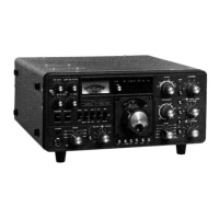
Controls for selecting operating mode and frequency bands.

Receive and Tuning Controls

Controls for receiver gain, selectivity, tuning, and clarifier.

Transmitter and Operation Controls

Controls for transmitter tuning, carrier, VOX, and processor.

Function and Accessory Switches

Switches for power, heaters, accessories, and special functions.

REAR APRON CONNECTIONS

INSTALLATION

MOBILE INSTALLATION

Procedures and considerations for installing the transceiver in a mobile environment.

OPERATION

Initial Checks and Frequency Selection

Pre-operation checks for damage, module seating, and voltage settings.

Receive Operations

Step-by-step procedure for operating the transceiver in receive mode.

Transmitter Operations

Procedure for tuning the transmitter for optimal output power and performance.

Frequency Control Systems

Explanation of memory system and switch operations for frequency control.

PART DESIGNATIONS ON CIRCUIT BOARDS

SIGNAL TRACING IN THE FT-901

THEORY OF OPERATION

RECEIVER THEORY

Explanation of the receiver circuit's signal path and components.

TRANSMIT CIRCUIT THEORY

Overview of the transceiver's signal path during transmission.

SSB TRANSMIT CIRCUIT

Detailed explanation of the SSB transmission signal path.

CW, FSK, AM, FM TRANSMIT CIRCUIT

Explanation of transmission path for CW, FSK, AM, and FM modes.

CW OPERATION THEORY

Explanation of CW mode operation and keying principles.

KEYER UNIT THEORY (PB-1728)

Description of the built-in electronic keyer circuit.

POWER SUPPLY

OUTER COVER REMOVAL

FRONT PANEL REMOVAL

FRONT PANEL SWITCH ASSEMBLY

KEYER, MEMORY UNIT INSTALLATION

AM/CW FILTER INSTALLATION

DC-DC CONVERTER INSTALLATION

FM UNIT INSTALLATION

COOLING FAN INSTALLATION

SOLDERING AND DESOLDERING TECHNIQUE

CIRCUIT TRACE REPAIR

MODIFICATIONS

MAINTENANCE AND ALIGNMENT

SAFETY WARNINGS AND PRECAUTIONS

Critical safety warnings and precautions for working on the transceiver.

S-METER SENSITIVITY ADJUSTMENT

Procedure for adjusting the S-meter sensitivity.

RECEIVER ADJUSTMENTS

Adjustments for VOX, CW sidetone, carrier balance, and IF passband tuning.

TRANSMITTER ADJUSTMENTS

Adjustments for AMGC, carrier frequency, ALC, speech processor, and bias.

FINAL STAGE ALIGNMENT AND NEUTRALIZATION

Procedures for neutralizing and aligning the final amplifier stages.

FAULT IDENTIFICATION AND LOCALIZATION

TROUBLESHOOTING FUNDAMENTALS

Systematic approach to identifying and locating faults in electronic equipment.

TYPICAL PART FAILURES, CAUSES, AND SYMPTOMS

Table summarizing common part failures, their causes, and resulting symptoms.

RECEIVE MODE TROUBLESHOOTING

Troubleshooting steps for issues related to receive mode operation.

TRANSMITTER TROUBLESHOOTING

Troubleshooting steps for transmitter power, performance, and meter issues.

COMMON CIRCUITS TROUBLESHOOTING

Troubleshooting steps for common circuits like counter, PLL, and indicators.

RF UNIT (PB-1702B)

NB/PROC UNIT (PB-1703C)

FILTER UNIT (PB-1716C)

IF UNIT (PB-1704C)

AF UNIT (PB-1705A)

VOX/MARKER UNIT (PB-1846)

CARRIER UNIT (PB-1706A)

VFO ASSEMBLY

FM UNIT (PB-1707B)

PLL UNIT (PB-1709A)

VCO UNIT (PB-1710B)

XTAL UNIT (PB-1711A)

DRIVER/FINAL AMPLIFIER STAGES

RECT A UNIT (PB-1708A)

RECT B BOARD/CAPACITOR BOARD

RECT C UNIT (PB-1717A)

COUNTER (PB-1729A)/DISPLAY (PB-1730) UNIT

MEMORY UNIT (PB-1787C)

LEVER SWITCH BOARD (PB-1719B)

LED A BOARD (PB-1721B)

SELECT SWITCH BOARD (PB-1718C)

TUNE SWITCH BOARD (PB-1720B)

KEYER UNIT (PB-1728A)

TRIMMER A BOARD (PB-1723C)

TRIMMER B BOARD (PB-1724C)

TRIMMER C BOARD (PB-1092-3330)

REJECT SWITCH BOARD

DIODE SWITCH BOARD (PB-1726A)

Related product manuals