Do you have a question about the Yaesu FTDX-9000D and is the answer not in the manual?
| Voltage | 13.8 V DC |
|---|---|
| Receiver Type | Triple Conversion Superheterodyne |
| Antenna Connector | SO-239 |
| Modes | SSB, CW, AM, FM, RTTY, PSK |
| Power Output | 200 W |
| Receiver Dynamic Range | >100 dB |
| Power Supply | External |
Provides guidance on how to use the manual and understand its conventions for optimal operation.
Explains the typographical conventions used for operational commands, texts, and notations within the manual.
Describes the features and normal operational characteristics of the FT DX 9000D's TFT display unit.
Details the procedure for connecting AC power to the transceiver and turning it on, including front and rear panel switches.
Explains the importance of setting the local time for correct operation of certain transceiver functions like World Clock.
Guides the user on how to access and modify transceiver settings via the Menu system for personalized operation.
Describes how to connect and select the microphone input, detailing options for front panel XLR and rear panel 8-pin connectors.
Provides instructions on how to extend the front feet of the transceiver to elevate the front panel for better viewing.
Explains how to adjust the physical resistance or drag of the Main Tuning Dial for user preference.
Outlines the procedure for a complete power cycle to re-initialize circuits after AC power fluctuations or interruptions.
Details procedures for resetting memory channels only, menu settings to factory defaults, or performing a full reset of all settings.
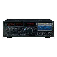
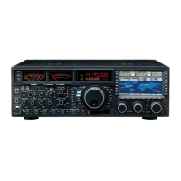
Highlights the ergonomic panel layout, large frequency display, S-meters, and multi-colored VFD display for visibility.
Describes key internal components like the HRDDS oscillator, OCXO, and the triple-conversion IF structure for performance.
Details features like narrow-bandwidth RF filters, noise reduction, AF limiter, and ultra-linear Class-A operation.
Covers the professional-grade microphone connector and the inclusion of a Compact Flash card for data storage.
Lists the items included with the transceiver, such as the FH-2 remote control keypad and CF card.
Showcases optional accessories like desk microphones, stereo headphones, and external speakers that enhance transceiver functionality.
Discusses antenna impedance matching, SWR limits, and the importance of using 50-Ohm coaxial cable for efficient antenna systems.
Explains the necessity and methods for establishing an effective ground system for electrical safety and optimal station performance.
Illustrates the proper connection of antenna coaxial cables and the AC power cable to the transceiver's rear panel.
Details how to connect microphones, the FH-2 remote control keypad, and a GPS receiver to the transceiver's various jacks.
Explains how to connect CW keys, keyers, and computer interfaces to the front and rear panel KEY jacks.
Describes how to connect a GPS receiver to the COM port to enable automatic location updates on the TFT display's World Map.
Provides instructions for connecting the FT DX 9000D to the VL-1000 Linear Amplifier for integrated operation.
Explains the function of the control cable for automatic amplifier tuning and power switch linking.
Details the modification required for the control cable, involving cutting an RCA connector and installing a 7-pin DIN connector.
Guides on how to connect the transceiver to linear amplifiers for TX/RX switching and ALC voltage adjustment.
Describes the function of essential front panel controls like the MOX, VOX, DIM, PHONES, and POWER switches for basic operation.
Details the function of front panel controls for keyer input, microphone connection, antenna tuner activation, and intercept point optimization.
Explains the function of controls for selecting meter functions, monitoring transmit audio, and adjusting AGC and RF attenuator settings.
Details the operation of Noise Blanker, Variable RF Filter, µ-Tune, and Notch filters for interference suppression.
Explains the function of Digital Notch Filter, Contour filter, and Digital Noise Reduction controls for signal enhancement.
Describes how to select operating modes, use the Quick Memory Bank, and interpret RX/TX indicators for band selection.
Explains the function of the Main Tuning Dial, FAST/LOCK switches, NAR filter, and SPLIT operation for frequency management.
Details controls for memory management, band switching, and various status indicators like busy, tuning offset, and split.
Explains the function of indicators for dual receive, high SWR, S-meters for signal strength, and the main/sub frequency displays.
Describes the controls for sub-band roofing filters, attenuator, VRF filter, and notch filter for interference rejection.
Covers controls for setting transmitter power output, engaging Class-A operation, and using the CF card slot for configuration.
Details switches for audio playback, AF limiter, IF shift/width, adjacent channel monitor, and memory/group selection.
Explains the dual function of the CLAR/VFO-B knob for clarifier offset and band/frequency selection.
Describes keys for frequency entry, band selection, mode selection, and VFO switching for flexible operation.
Details the main antenna connectors, RX antenna input, main power switch, AC input, and circuit breaker.
Describes rear panel ports for RTTY, Packet, external speakers, AF output, and +13.8V supply.
Covers rear panel connectors for CAT control, GPS input, keyboard interface, and future expansion ports.
Explains the indicators for Main band transmit/receive status and frequency display.
Explains the indicators for Sub band transmit/receive status and frequency display.
Describes the multi-panel display fields for clarifier offset, memory recall, memory tune, and repeater shift data.
Guides on pre-operation checks including grounding, antenna connection, microphone setup, and initial AF gain settings.
Explains how to use the LOCK, DIM, and B-DISP OFF controls for frequency, display brightness, and sub-band display management.
Details how to enable and adjust dual receive for simultaneous monitoring of two frequencies and modes.
Explains Full Duplex operation and various diversity reception modes for enhanced signal reception.
Covers headphone audio mixing for dual receive and sideband diversity reception for AM signals.
Describes bandwidth diversity for channel perception and polarity diversity for using different antennas.
Explains the audio playback feature and the 'My Bands' function for customizing band selection.
Details the band stack feature allowing storage of multiple frequencies and modes per band for quick selection.
Describes how to reconfigure the AF/RF Gain knobs for combined control of Main and Sub receivers.
Explains how to assign a frequently used menu item to the C.S (Custom Switch) key for quick access.
Covers various methods for efficient frequency entry and navigation, including keyboard entry and microphone controls.
Details how to select the desired antenna for transmission and reception using the front panel switches.
Guides on how to configure the audio output to internal speakers for stereo or monaural modes.
Provides an overview of the receiver's front-end and DSP filtering capabilities for interference suppression and signal clarity.
Explains how to use the IPO function to optimize receiver front-end characteristics for strong signal environments by bypassing the RF amplifier.
Details the use of the ATT knob to insert RF attenuation, reducing signal strength for reception in noisy conditions.
Explains how to manually adjust RF gain for optimal receiver sensitivity and noise level management.
Describes the operation of the µ-Tune system for ultra-sharp RF selectivity, including manual adjustment and its benefits.
Explains the VRF system for high-performance RF preselection, offering broad interference rejection with lower insertion loss.
Compares the performance of µ-Tune and VRF filters against typical fixed bandpass filters, highlighting selectivity advantages.
Details the use of narrow-band roofing filters to protect receiver circuitry and improve reception on crowded bands.
Explains the Contour filter's ability to suppress or enhance frequency components for a more natural audio response.
Describes how the IF Shift control adjusts the DSP filter passband to reduce or eliminate interference.
Explains how the WIDTH control varies the DSP IF passband width to eliminate interference or enhance signal fidelity.
Details the IF Notch filter's function for slicing out interfering beat notes or carrier signals from the receiver passband.
Explains the DNR system's use of algorithms to reduce random noise, effective for SSB operation.
Describes the NAR switch for quick, mode-specific selection of a narrow IF DSP filter setting.
Explains the Auto-Notch feature of the DNF filter for cancelling interfering beat notes without adjustment.
Details the IF Noise Blanker's function to reduce impulse noise caused by automotive ignition systems.
Explains the AGC system's role in maintaining constant audio output by compensating for signal variations and preventing overload.
Describes the Sloped AGC system, which allows audio volume to rise slightly with signal strength for better signal separation.
Explains the Mute feature for silencing the Main receiver and the AF Limiter (AFL) for controlling audio output levels.
Details the ACM feature for visually indicating signal encroachment on CW, displayed on the Sub-receiver's S-meter.
Guides on selecting operating modes (LSB, USB, AM) and configuring microphone gain and input for SSB/AM transmission.
Provides instructions for enabling 48V phantom power for condenser microphones via the XLR connector, with safety precautions.
Explains how to operate the built-in Automatic Antenna Tuner (ATU) to match impedances and minimize SWR.
Provides step-by-step instructions for replacing the ATU backup battery, ensuring memory retention.
Explains the Speech Processor's function to increase talk power and improve intelligibility through compression.
Guides on varying the transmitted bandwidth for different levels of fidelity or talk power in SSB operation.
Details the Three-Band Parametric Microphone Equalizer for precise control over audio frequency response.
Explains Class-A operation for ultra-low distortion, detailing power output and bias adjustments for improved SSB waveform.
Describes the Voice Memory capability using the FH-2 keypad for storing and playing back voice messages.
Explains VOX for hands-free transmission and the Monitor feature for checking transmitted signal quality.
Details Split Frequency operation using TX Clarifier and Full Duplex capability for simultaneous transmit/receive on different bands.
Covers Split Operation using TX Clarifier and the Quick Split feature for setting a +5 kHz transmit offset.
Explains the unique Full Duplex capability for crossband transmit/receive, useful for DX-pedition and contest operations.
Guides on setting up for straight key operation or emulation using the front/rear panel KEY jacks and the KEYER switch.
Details how to use the built-in electronic keyer, including speed adjustment and the BK-IN/SPOT switch for semi-break-in.
Explains how to use CW Reverse mode to receive on the opposite sideband for interference rejection.
Covers CW delay time setting, CW pitch adjustment for receiver passband, and CW spotting for frequency alignment.
Details operations for programming CW messages into memory, checking contents, and on-air playback.
Explains text memory storage for CW messages and contest number programming/decrementing.
Guides on programming text messages, correcting stored characters, and deleting previously stored data.
Provides instructions for utilizing the transceiver with FM repeaters, including CTCSS tone setup and shift direction.
Explains the transceiver's memory system, including regular memories, PMS pairs, QMB memories, and memory grouping.
Details the procedure for storing and recalling settings using the five QMB channels for quick access.
Guides on enabling memory groups and selecting a desired group to limit memory recall to specific sets of channels.
Explains the process of storing current settings into memory channels and recalling them for later use.
Covers checking memory contents, erasing data, and transferring memory data to the Main VFO.
Details transferring memory data to VFO-A and using Memory Tune mode for flexible frequency adjustments.
Explains how to enable and use the transceiver for emergency communications on the Alaska Emergency Frequency 5167.5 kHz.
Guides on operating on the 60-meter band using pre-programmed memory channels.
Describes how to perform VFO scanning and memory scanning to find active signals, with options for scan resume.
Explains the PMS feature for limiting scanning and manual tuning within specific frequency ranges using memory pairs.
Details the setup procedures for Packet operation, including connection to a TNC and basic configuration settings.
Explains the setup for RTTY operation using a TNC or computer, covering mode selection and polarity settings.
Provides guidance on setting up the transceiver for various other SSB-based data modes, using the illustration as a reference.
Guides on accessing the Menu system, making adjustments, saving settings, and performing a factory reset of menu parameters.
Lists and describes the menu items related to Automatic Gain Control (AGC) settings for both Main and Sub receivers.
Covers menu items for TFT color, dimmer settings, bar display selection, and dial step adjustments.
Details menu options specific to operating modes like AM, CW, FM, Packet, RTTY, and SSB for microphone, carrier, and bandwidth adjustments.
Explains menu items for receiver DSP filters (Contour, Notch, Narrow) and audio settings like AGC slope and headphone mix.
Details menu items for transmitter power control, external amplifier settings, full duplex, VOX, and emergency frequency TX.
Lists general operating parameters, frequency ranges, stability, temperature, emission modes, and power consumption.
Provides detailed specifications for the transmitter, including power output, modulation types, and harmonic radiation.
Details receiver specifications such as circuit type, intermediate frequencies, sensitivity, and selectivity.