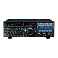
Do you have a question about the Yaesu FTDX5000 and is the answer not in the manual?
Lists accessories included with the transceiver.
Lists optional accessories available for purchase.
Instructions for connecting the transceiver to AC power.
Guide on how to extend the transceiver's front feet.
Procedure for adjusting the feel of the main tuning dial.
Steps for resetting memories, menu settings, or performing a full reset.
Guidance on selecting and connecting antennas for optimal performance.
Information on using appropriate coaxial cable for connections.
Importance and methods for establishing an effective ground system.
Instructions for connecting antenna and power cables.
Diagrams for connecting microphone and headphone.
Details on connecting CW keying devices and computer interfaces.
Guide for connecting the VL-1000 linear amplifier.
Information on connecting to external linear amplifiers.
Details on POWER switch, CAT indicator, PHONES, KEY jacks, and Mic connector.
Explanation of DIM, MOX, VOX, TUNE, MONI, PROC, RX ANT, ANT 1-4 switches.
Information on ATT, IPO, and R.FLT controls for receiver input.
Details on AGC, METER, MONI/PROC knobs, and NB/SQL knobs.
Explanation of MIC and RF PWR knobs for audio and power adjustment.
Details on SPEED/PITCH, VOX/DELAY, and AF/RF GAIN controls.
Explanation of A/B, AB, V/M, MA, AM, and MENU switches.
Details on SPLIT, TXW, CLASS-A, C.S, VFO RX/TX, Main Tuning Dial, FAST, LOCK, BAND, MODE.
Explanation of AB, BAND/MCH, A/B, VFO-B RX/TX, CLAR(VFO-B), SUB DISPLAY-II.
Details on CLAR/GRP, RX CLAR/FAST, CLEAR, TX CLAR/LOCK controls.
Explanation of VFO-A DSP controls like NOTCH, WIDTH, DNR, DNF, and SELECT.
Details on VFO-B DSP controls like CONT/APF, NOTCH, WIDTH, DNR, SELECT, DNF.
Explanation of VFO-A block diagram and status indicators.
Explanation of VFO-B block diagram and status indicators.
Details on VFO-A frequency display and various indicators.
Details on IF OUT, ANT jacks, RX ANT IN, GND, μ-TUNE, ROTATOR, BAND DATA, PACKET, RTTY.
Information on AF OUT, V-AF, EXT SPKR, E.ALC, PTT, TRV, EXT ALC, TX GND connections.
Details on MIC, REC, TX REQ, +13.8V, KEY, Power, Circuit Breaker, AC IN, DMU, CAT, PGM, REMOTE.
Explanation of the controls on the FH-2 remote keypad.
Precautions, LOCK, and DIM settings before starting operation.
Using tuning dials, buttons, AF GAIN, RX, SQL, and scanning.
Steps for BAND/MCH, frequency tuning, antenna, mode, squelch, and dial.
How to use the Clarifier function for VFO-A frequency offset.
Graphical representation of the Clarifier offset.
Using VFO-A and VFO-B receivers simultaneously.
Bandwidth diversity and polarity diversity reception.
Recording and playback of the last 15 seconds of receiver audio.
Customizing band selection to skip unused bands.
Storing multiple frequencies and modes per band.
Programming a front panel button for quick Menu access.
Controlling a rotator from the transceiver.
Using keyboard entry, Up/Down buttons, and microphone/keypad switches.
Covers VRF, R.FLT, CONTOUR, IF SHIFT, IF WIDTH, IF NOTCH, DNR, DNF, AGC, SLOPED AGC.
Optimizing receiver front-end characteristics for noise and signal strength.
Using the ATT button to insert RF attenuation.
Manually adjusting receiver RF and IF stages gain.
Description and operation of the VRF system.
Using IF roofing filters for bandpass protection.
Adjusting the receiver passband shape for signal enhancement.
Varying the DSP filter passband center frequency.
Adjusting the width of the DSP IF filter passband.
Combining IF Shift and Width for effective interference filtering.
Using the IF Notch filter to remove interfering signals.
Reducing random noise using DNR algorithms.
Using the Auto-Notch filter to cancel interfering beat notes.
Engaging narrow IF DSP filters with a single button press.
Reducing pulse noise using the IF Noise Blanker.
Understanding and setting the AGC system.
Using the Sloped AGC system for better signal separation.
Silencing the VFO-A receiver temporarily during Dual Receive.
Independent control of low and upper audio ranges.
Steps for selecting modes, setting gain, and transmitting.
Steps for operating the Automatic Antenna Tuner.
Detailed procedure for ATU tuning and operation.
Explanation of ATU functionality and memory.
Precise control over low, mid, and treble ranges of voice waveform.
Steps to engage the Parametric Microphone Equalizer.
Detailed setup process for the equalizer.
Step-by-step guide to activating the equalizer.
Increasing talk power and improving intelligibility.
Yieding ultra-low distortion products during SSB operation.
Using the FH-2 keypad for voice memory storage and playback.
Hands-free, automatic transmitter activation via voice.
Listening to transmitted signal quality using the Monitor feature.
Using TX Clarifier for split TX/RX operation.
Visual depiction of the relative offset of the Clarifier.
Flexible split frequency operation using VFO-A and VFO-B.
Synchronizing VFO-A and VFO-B frequency tuning.
One-touch offset of +5 kHz for transmit frequency.
Connecting and setting up straight key or computer keying.
Connecting and operating the built-in electronic keyer.
Configuring the transceiver for full break-in (QSK) CW operation.
Adjusting the dot/space to dash ratio for the electronic keyer.
Configuring keyer modes like OFF, BUG, ELEKEY, ACS.
Ensuring precise frequency alignment with other stations.
Trying the opposite sideband to eliminate interference.
Using the APF to narrow audio bandwidth and reduce interference.
Adjusting transmitter hang time for semi-break-in operation.
Setting the receiver passband and CW carrier tone pitch.
Storing and transmitting CW messages for contests.
Storing messages using the keyer paddle.
Verifying stored CW memory contents.
Transmitting stored CW messages.
Setting up automatic repetitive beacon messages.
Programming CW messages using text entry.
Steps for programming messages via text entry.
Setting or resetting the contest number.
Reducing the contest number by one.
Steps for selecting FM mode and tuning frequency.
Setting up for repeater operation with CTCSS and shifts.
Detailed steps for basic FM operation.
Detailed steps for repeater setup.
Overview of memory storage capabilities.
Using the Quick Memory Bank for fast recall.
Storing and recalling regular memory channels.
Organizing memories into groups for easier access.
Scanning through frequencies in the VFO.
Scanning through stored memory channels.
Configuring the radio for packet operation.
Initial setup steps for packet mode.
Configuration steps for RTTY mode.
Initial setup for RTTY operation.
Steps to set up the transceiver for transverter use.
Adjusting the display to show transverter frequencies.
How to operate the transceiver in transverter mode.
Guide to navigating and adjusting menu items.
Procedure to reset all menu settings to factory defaults.
General specifications including frequency range, stability, and power.
Transmitter specifications including power output and modulation.
Receiver specifications including sensitivity, selectivity, and IF stages.
| Power Output | 5-200 Watts |
|---|---|
| Receiver Type | Triple Conversion Superheterodyne |
| Impedance | 50 Ohms |
| RF Output Power | 5-200 Watts |
| Supply Voltage | 13.8 V DC ±15% |
| Dynamic Range | 112 dB |
| Voltage | 13.8 VDC |
| Modes | AM, FM, RTTY, PSK |
| Display | TFT |
| Output Power | 200W |
| IF Bandwidth | 15 kHz (AM) |