Do you have a question about the Yaesu FTDX101MP and is the answer not in the manual?
Explains how pressing the [C.S] key operates the MPVD ring.
Explains the steps to assign functions to the MPVD ring.
Explains the QSK DELAY TIME setting in CW mode.
Explains how to select transmit audio input in SSB mode.
Explains how to select transmit audio input in AM mode.
Explains how to select transmit audio input in FM mode.
Explains how to select transmit audio input in DATA mode.
Explains how to select items on the Function Screen.
Describes the hybrid SDR configuration.
Details the three types of roofing filters.
Explains the new 3DSS/Hybrid Dual SDR Display.
Describes the TFT display with touch functionality.
Explains how the Filter Function Display works.
Discusses RF pre-selector and VC-TUNE.
Explains the two selectable RF stages.
Describes WIDTH and SHIFT features for signal elimination.
Explains the CONTOUR feature for noise reduction.
Details the DNR function.
Explains NOTCH and DNF features.
Describes the Active Band Indicator.
Explains the MPVD outer dial.
Discusses the high-output final amplifier stage.
Explains safety marks and their meanings.
Explains safety symbols and their meanings.
Lists the accessories included with the transceiver.
Lists optional accessories available for purchase.
Discusses factors for connecting antennas.
Explains how to connect antennas and coaxial cables.
Details how to connect power cables.
Explains DC power cable connection for USA version.
Provides general guidelines for installing the transceiver.
Details microphone and its related connections.
Explains headphone connection.
Describes key and keyer connections.
Details the FH-2 remote control keypad.
Explains how to connect the VL-1000 amplifier.
Details how to interface with other linear amplifiers.
Describes the cooling fan.
Explains ANT connectors.
Describes the external speaker jack.
Explains the KEY jack.
Describes the AF-OUT jack.
Explains the REM jack for FH-2 control.
Describes the RTTY/DATA jack.
Explains the METER jack.
Describes the EXT ALC input jack.
Explains the USB jack.
Describes the RS-232C serial jack.
Explains the GND terminal.
Describes the DC power input.
Explains the RX OUT (MAIN) jack.
Describes the LINEAR jack.
Explains the ACC jack.
Describes the IF OUT (MAIN) jack.
Explains the TX-GND jack.
Describes the PTT input jack.
Explains the RX OUT (SUB) jack.
Describes the +13.8V output jack.
Explains the TUNER jack.
Describes the EXT-DISPLAY connector.
Explains the IF OUT (SUB) jack.
Explains the PTT switch function.
Describes the DWN/UP keys.
Explains the MUTE key function.
Provides instructions for using the microphone.
Explains the P1-P4 key functions.
Explains how to use the VC TUNE feature.
Describes the Band Pass Filter.
Explains how to use the roofing filter.
Discusses DSP interference removal functions.
Shows meter and filter indications.
Explains the frequency display area.
Shows function settings.
Explains the spectrum scope.
Lists display setting keys.
Explains meter operations during transmission.
Describes meter operation during transmit.
Shows AMC gain control display.
Shows only DSP filter bandwidth information.
Explains keyboard frequency entry.
Describes tuning in 1 MHz or 1 kHz steps.
Explains how to switch antennas.
Describes the attenuator function.
Explains the IPO function.
Describes the roofing filter switching.
Explains the AGC function.
Switches Spectrum Scope operation.
Explains CENTER mode for spectrum scope.
Explains CURSOR mode for spectrum scope.
Explains FIX mode for spectrum scope.
Describes setting the scope span.
Switches between 3DSS and waterfall display.
Explains mono/dual display switching.
Explains the MULTI knob operations.
Describes EXPAND function for scope display.
Explains HOLD function for scope display.
Describes DISP key for scope screen display.
Accesses scope menu for settings.
Sets scope display sweep speed.
Adjusts peak signal color density.
Displays markers for frequencies.
Changes scope display color.
Adjusts reference level for signal distinction.
Explains the operation of the MULTI knob.
Explains the ON/OFF switch.
Describes the USB jack.
Explains the KEY jack.
Describes the PHONES jack.
Explains the MIC jack.
Explains the TUNE switch.
Describes the VOX function.
Explains the MOX key.
Describes ZIN and SPOT functions.
Mentions the SD memory card slot.
Explains the FAST key.
Describes the LOCK key.
Explains fine tuning in 1 Hz steps.
Explains how to store QMB channels.
Describes how to recall QMB channels.
Explains how to view QMB contents.
Describes changing the number of QMB channels.
Explains how to mark the operation band.
Explains RX operation on the MAIN band.
Describes TX operation on the MAIN band.
Explains switching between MAIN and SUB bands.
Describes TX operation on the SUB band.
Explains RX operation on the SUB band.
Refers to dial knobs for band switching.
Explains the MAIN AF knob.
Describes the RF/SQL knob.
Explains how to switch RF/SQL knob operation.
Explains the SUB AF knob.
Describes the SUB RF/SQL knob.
Explains the MIC/SPEED knob.
Describes the PROC/PITCH knob.
Explains the Noise Blanker (NB) function.
Details how to adjust noise attenuation.
Explains how to reduce pulse noise.
Describes setting MULTI knob for NB level adjustment.
Explains the Digital Noise Reduction (DNR).
Describes the Digital NOTCH Filter (DNF).
Explains the IF NOTCH Filter.
Explains the Contour filter.
Details how to adjust Contour circuit gain.
Explains setting Contour circuit bandwidth.
Explains the Audio Peak Filter (APF).
Describes SHIFT and WIDTH functions.
Explains the WIDTH knob.
Explains the NOTCH inner knob.
Describes the CONT/APF outer knob.
Explains how to adjust microphone gain.
Details how to adjust AMC gain.
Explains the Speech Processor.
Describes RF power output control.
Explains the Parametric Microphone Equalizer.
Details how to set up the equalizer.
Explains how to activate the equalizer.
Explains how to record voice in memory.
Describes how to check recorded voice.
Explains how to transmit recorded messages.
Explains how to operate the ATU.
Explains how to adjust sidetone audio level.
Describes CW delay time setting.
Explains CW decode function.
Describes CW spotting technique.
Explains how to adjust keyer speed.
Details keyer weight adjustment.
Explains reversing keyer polarity.
Describes selecting keyer operating modes.
Explains contest memory keyer function.
Describes message memory.
Explains storing messages into memory.
Details message memory programming.
Explains how to check CW memory contents.
Describes on-the-air CW message playback.
Explains transmitting in beacon mode.
Explains TEXT memory.
Details text message programming on TFT screen.
Explains text message programming via FH-2.
Describes text input procedure.
Describes RTTY text playback.
Explains how to check CW memory contents.
Explains contest number programming.
Details contest number programming.
Explains how to decrement contest numbers.
Describes on-the-air CW message playback.
Explains transmitting in beacon mode.
Explains repeater operation.
Describes tone squelch operation.
Explains connecting to a PC for RTTY.
Describes connecting to a TU.
Explains threshold level adjustment for RTTY decode.
Details text message programming on TFT screen.
Explains text message programming via FH-2.
Describes text input procedure.
Describes RTTY text playback.
Explains connecting to a PC for PSK.
Describes connecting a data communications device.
Explains threshold level adjustment for PSK decode.
Details text message programming on TFT screen.
Explains text message programming via FH-2.
Describes text input procedure.
Describes PSK text playback.
Explains how to store memory channels.
Describes erasing memory channel data.
Explains how to check memory channel status.
Toggles frequency control between VFO and memory.
Explains how to recall memory channels.
Describes memory tune operation.
Explains moving memory data to VFO.
Describes labeling memory channels.
Explains how to display memory tags.
Describes scan skip setting.
Explains how to choose a memory group.
Explains VFO/Memory scanning.
Explains band stack operation.
Describes the Time Out Timer (TOT).
Explains MULTI knob step increment settings.
Details operation on Alaska Emergency Frequency.
Explains how to capture the screen.
Explains how to install the SD card.
Describes how to remove the SD card.
Explains how to format an SD card.
Details adjusting date and clock.
Explains saving memory and menu data to SD card.
Explains reading memory and menu data from SD card.
Describes how to display SD card information.
Explains how to use the menu.
Details how to reset setting menus.
Sets AGC-FAST DELAY for SSB.
Sets AGC-MID DELAY for SSB.
Sets AGC-SLOW DELAY for SSB.
Sets low-frequency cutoff for SSB audio.
Sets low-frequency cutoff slope for SSB.
Sets high-frequency cutoff for SSB audio.
Sets high-frequency cutoff slope for SSB.
Selects SSB output band setting.
Sets receive SSB signal output level.
Selects audio passband for SSB modulator.
Selects transmit audio input jack for SSB.
Selects input jack for SSB signal.
Sets SSB signal input level for REAR.
Sets PTT control for SSB transmit.
Sets AGC-FAST DELAY for AM.
Sets AGC-MID DELAY for AM.
Sets AGC-SLOW DELAY for AM.
Sets low-frequency cutoff for AM audio.
Sets low-frequency cutoff slope for AM.
Sets high-frequency cutoff for AM audio.
Sets high-frequency cutoff slope for AM.
Selects AM output band setting.
Sets receive AM signal output level.
Selects audio passband for AM modulator.
Selects transmit audio input jack for AM.
Sets microphone gain for AM mode.
Selects input jack for AM signal.
Sets AM signal input level for REAR.
Sets PTT control for AM transmit.
Sets AGC-FAST DELAY for FM.
Sets AGC-MID DELAY for FM.
Sets AGC-SLOW DELAY for FM.
Sets low-frequency cutoff for FM audio.
Sets low-frequency cutoff slope for FM.
Sets high-frequency cutoff for FM audio.
Sets high-frequency cutoff slope for FM.
Selects FM output band setting.
Sets receive FM signal output level.
Selects transmit audio input jack for FM.
Sets microphone gain for FM mode.
Selects input jack for FM signal.
Sets FM signal input level for REAR.
Sets PTT control for FM transmit.
Sets AGC-FAST DELAY for PSK/DATA.
Sets AGC-MID DELAY for PSK/DATA.
Sets AGC-SLOW DELAY for PSK/DATA.
Sets the PSK tone.
Sets carrier point in DATA mode.
Sets low-frequency cutoff for DATA audio.
Sets low-frequency cutoff slope for DATA.
Sets high-frequency cutoff for DATA audio.
Sets high-frequency cutoff slope for DATA.
Selects DATA signal output band.
Sets receive DATA signal output level.
Selects audio passband for DATA modulator.
Selects transmit audio input jack for DATA.
Selects input jack for DATA signal.
Sets DATA signal input level for REAR.
Sets PTT control for DATA transmit.
Enables/Disables RX USOS feature.
Enables/Disables TX USOS feature.
Selects command code for Carriage Return.
Enables/Disables sending Carriage Return.
Selects transmission code when no character.
Selects Baudot Code for RTTY mode.
Selects operation mode for PSK.
Selects operation range of AFC feature.
Sets QPSK Decode Phase Shift Direction.
Sets QPSK Encode Phase Shift Direction.
Sets data output level for PSK.
Sets AGC-FAST DELAY for CW.
Sets AGC-MID DELAY for CW.
Sets AGC-SLOW DELAY for CW.
Sets low-frequency cutoff for CW audio.
Sets low-frequency cutoff slope for CW.
Sets high-frequency cutoff for CW audio.
Sets high-frequency cutoff slope for CW.
Selects CW signal output band.
Sets CW signal output level.
Enables/disables CW keying while operating SSB.
Sets CW brake-in function.
Sets CW delay time.
Selects CW carrier wave-form shape.
Sets the PITCH frequency offset.
Sets RTTY/DATA jack for PC keying.
Sets time delay before transmitting keying signal.
Shows bar display settings in CW mode.
Selects keyer operation mode for front panel KEY jack.
Reverses CW paddle connections for front panel.
Selects keyer operation mode for rear panel KEY jack.
Reverses CW paddle connections for rear panel.
Adjusts keyer CW weight.
Selects contest number format.
Enters initial contest number.
Selects registration method for CW MEMORY 1.
Selects registration method for CW MEMORY 2.
Selects registration method for CW MEMORY 3.
Selects registration method for CW MEMORY 4.
Selects registration method for CW MEMORY 5.
Sets interval between beacon message repetitions.
Selects AFC feature bandwidth.
Sets band to decode in CW, RTTY, PSK.
Selects audio mixing modes for headphones.
Operation selections for ANT 3/RX connector.
Sets duration of noise blanking pulse.
Selects level of noise attenuation.
Sets beep volume level.
Selects operation mode of RF/SQL knob.
Selects internal/external antenna tuner settings.
Sets baud rate for RS-232C jack CAT input.
Sets Time-Out Timer for RS-232C command input.
Sets baud rate for CAT command input of USB jack.
Sets Time-Out Timer for CAT command input.
Configures CAT RTS port setting.
Sets number of channels for Quick Memory bank.
Sets memory group function.
Inputs a Quick Split offset frequency.
Selects frequency offset for Quick Split.
Sets bandwidth of Audio Peak Filter.
Adjusts GAIN of the CONTOUR circuit.
Sets bandwidth ("Q") of CONTOUR circuit.
Sets Digital Noise Reduction response.
Sets attenuation bandwidth of DSP IF notch filter.
Sets AMC and speech processor compression level.
Sets AMC level adjustment tracking speed.
Sets center frequency for low range parametric EQ.
Sets gain for low range parametric EQ.
Sets bandwidth ("Q") for low range parametric EQ.
Sets center frequency for middle range parametric EQ.
Sets gain for middle range parametric EQ.
Sets bandwidth ("Q") for middle range parametric EQ.
Sets center frequency for high range parametric EQ.
Sets gain for high range parametric EQ.
Sets bandwidth ("Q") for high range parametric EQ.
Sets low range freq for EQ when AMC/SP is ON.
Sets low range gain for EQ when AMC/SP is ON.
Sets low range bandwidth for EQ when AMC/SP is ON.
Sets transmit RF power for HF band.
Sets transmit RF power for 50 MHz band.
Sets transmit RF power for 70 MHz band.
Sets transmit RF power for AM mode.
Selects function of VOX operation.
Sets VOX GAIN for data operations.
Enables TX/RX on Alaska Emergency Channel.
Sets MAIN dial tuning speed in SSB/CW.
Sets MAIN dial tuning speed in RTTY/PSK.
Selects tuning steps for MULTI knob.
Selects tuning steps for AM mode.
Selects tuning steps for FM mode.
Sets step per rotation of MAIN dial.
Sets step per rotation of MPVD ring.
Programs a Call Sign or Name.
Sets time for displaying registered "MY CALL".
Sets time before screen saver activates.
Sets TFT contrast level.
Sets TFT display brightness level.
Sets key LED brightness level.
Sets mouse pointer movement speed.
Sets frequency display font.
Sets resolution of Spectrum Scope display.
Sets scope screen center and marker position.
Changes Waterfall Display sensitivity.
Changes 3DSS Display sensitivity.
Sets video signal output for EXT DISPLAY terminal.
Selects screen resolution for external monitor.
Set the date (Day).
Set the date (Month).
Set the date (Year).
Set the time (Hour).
Set the time (Minute).
Loads memory channel info from SD card.
Saves memory channel info to SD card.
Loads setting menu info from SD card.
Saves setting menu info to SD card.
Displays SD card capacity and free space.
Updates transceiver firmware.
Formats the SD memory card.
Displays touch position calibration.
Resets memory data.
Resets setting menu data.
Initializes all settings to factory default.
Resets memory channel data to factory default.
Resets setting menu data to factory default.
Initializes all settings to factory default.
Details the FC-40 antenna tuner.
Explains FC-40 interconnections to the transceiver.
Configures the transceiver for FC-40 operation.
Explains FC-40 automatic tuning operation.
Describes FH-2 voice memory channels.
Explains FH-2 cursor keys.
Describes the FH-2 LOCK switch.
Explains the FH-2 MEM key.
Describes the FH-2 DEC key.
Lists general specifications.
Lists transmitter specifications.
Lists receiver specifications.
Explains equipment symbols.
Instructions for online warranty registration.
Outlines the terms of the warranty.
Details limitations of the warranty coverage.
Provides procedures for warranty claims.
Identifies the equipment type.
Specifies the brand name.
States the model number.
Identifies the manufacturer.
Provides manufacturer's address.
Manufacturer's declaration statement.
Compliance statement for Canada.
Provides usage conditions for EU countries.
Instructions for proper disposal of equipment.
| Brand | Yaesu |
|---|---|
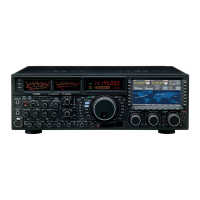
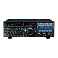
| Model | FTDX101MP |
| Category | Transceiver |
| Language | English |