Do you have a question about the Yaesu FTdx5000 Series and is the answer not in the manual?
Describes the VRF filter's function and manual tuning.
Details receiver performance and dual receive features.
Explains transmit side features like the microphone equalizer.
Lists advanced features like keyboard entry and multiple antenna ports.
Explains the universal power supply and connection.
Details extending feet, retracting feet, and adjusting dial torque.
Discusses impedance matching and antenna system requirements for optimal performance.
Advises on using high-quality 50-Ohm coaxial cable and connector types.
Explains the power switch, CAT indicator, and headphone jack.
Details the KEY jack and the 8-pin microphone connector.
Shows antenna, attenuation, filter, IPO, and roofing filter selections.
Indicates transmission, squelch, FAST tuning, lock status, mode, NAR, and NB.
Explains various indicators like MONI, KEYER, BK-IN, PROC, TUNER, HI-SW, CLAR, MR, MT.
Covers VFO-A Frequency Display and Tuning Offset Indicator.
Details IF OUT, ANT 1-4, and RX ANT IN jacks for RF signal handling.
Covers GND terminal for earthing and µ-TUNE jacks for optional kits.
Details jacks for rotators, band data, packet TNCs, and RTTY units.
Explains simultaneous reception on VFO-A and VFO-B.
Details connecting stereo headphones for dual reception audio.
Covers VFO tracking and sideband diversity reception modes.
Details how to configure the "My Bands" feature by selecting bands to skip.
Explains how to use the "My Bands" feature to select pre-configured bands.
Guides through assigning a Menu item to the [C.S] button.
Explains how to recall and adjust a programmed Menu item using the [C.S] button.
Allows direct entry of frequencies using front panel keys.
Tunes VFO frequency in 1 MHz steps using microphone or FH-2 buttons.
Uses microphone UP/DWN switches for scanning and tuning.
Uses FH-2 keypad buttons for VFO frequency adjustment.
Details VRF preselector and first IF roofing filters.
Explains Contour, IF Shift, and IF Width DSP filters.
Covers DNR, DNF, AGC, and Sloped AGC functions.
Describes the VRF preselector for superior out-of-band signal rejection.
Details the first IF roofing filters for interference protection.
Explains the Contour filter system for signal perturbation.
Maintains constant audio output level by adjusting signal strength.
Allows audio volume to rise and fall slightly with signal strength.
Guides through connecting the microphone and adjusting equalizer settings.
Stores and plays back voice messages using the FH-2 keypad.
Guides setup for using straight keys or computer keying.
Details using the transceiver's internal electronic keyer with a paddle.
Explains zero-beating with CW station using spotting tone.
Activates APF for very narrow audio bandwidth to reduce interference.
Stores messages using a keyer paddle or text entry.
Guides through selecting FM mode, tuning, and basic transmission.
Explains storage and recall of frequencies, modes, and settings.
Details the process of storing data into QMB memories.
Explains how to recall data from QMB memories.
Guides through enabling and assigning memory groups.
Explains how to recall memories within a specific group.
Scans VFO frequencies until a signal opens the squelch.
Details menu setup procedures and essential steps for packet operation.
Details the setup steps required before commencing RTTY operation.
Guides setting up the transceiver for transverter use and adjusting frequency display.
Explains how to navigate and operate the transceiver's menu system.
Resets all menu settings to original factory defaults.
Lists general specifications like frequency range, power consumption, and dimensions.
Lists transmitter specifications like power output and modulation types.
| Brand | Yaesu |
|---|---|
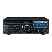
| Model | FTdx5000 Series |
| Category | Transceiver |
| Language | English |