Introduction
This manual provides technical information necessary for
servicing the FT
DX5000 Series HF/50 MHz Transceiver.
Servicing this equipment requires expertise in handling
surface-mount chip components. Attempts by non-qual-
ified persons to service this equipment may result in
permanent damage not covered by the warranty, and
may be illegal in some countries.
Two PCB layout diagrams are provided for each dou-
ble-sided circuit board in the Transceiver. Each side of
is referred to by the type of the majority of components
installed on that side (“leaded” or “chip-only”). In most
cases one side has only chip components, and the oth-
er has either a mixture of both chip and leaded compo-
nents (trimmers, coils, electrolytic capacitors, ICs, etc.),
or leaded components only.
While we believe the technical information in this manu-
al to be correct, VERTEX STANDARD assumes no lia-
bility for damage that may occur as a result of typograph-
ical or other errors that may be present. Your coopera-
tion in pointing out any inconsistencies in the technical
information would be appreciated.
©2011 VERTEX STANDARD CO., LTD. EH036H90C
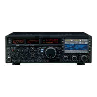
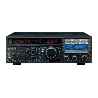
Technical Supplement
HF/50 MHz TRANSCEIVER
FTDX5000S
ERIES
Contents
Specifications
Exploded View & Miscellaneous Parts
Block Diagram
Connection Diagram
Alignment
Board Unit (Schematics, Layouts & Parts)
TRX Unit
VRF Unit
BPF Unit
SCP Unit
DVS Unit
RX-1 Unit
LOCAL Unit
CNTL Unit
PA-B Unit
TUNER Unit
TUNER-C Unit
ANT Unit
VRF-A Unit
DSP Unit
VR-A Unit
VR-B Unit
ENC Unit
BACK-LIGHT Unit
SW-A Unit
SW-B Unit
SW-C Unit
SW-D Unit
JACK Unit
MIC Unit
UEL Unit
LINK Unit
Important Note
1) This transceiver was assembled using Pb (lead) free solder,
based on the RoHS specification.
Only lead-free solder (Alloy Composition: Sn-3.0Ag-0.5Cu)
should be used for repairs performed on this apparatus. The
solder stated above utilizes the alloy composition required for
compliance with the lead-free specification, and any solder
with the above alloy composition may be used.
2) Risk of explosion if battery is replaced by an incorrect type.
Dispose of used batteries according to the instructions.
VERTEX STANDARD CO., LTD.
4-8-8 Nakameguro, Meguro-Ku, Tokyo 153-8644, Japan
VERTEX STANDARD
US Headquarters
10900 Walker Street, Cypress, CA 90630, U.S.A.
YAESU UK LTD.
Unit 12, Sun Valley Business Park, Winnall Close
Winchester, Hampshire, SO23 0LB, U.K.
VERTEX STANDARD HK LTD.
Unit 1306-1308, 13F., Millennium City 2, 378 Kwun Tong Road,
Kwun Tong, Kowloon, Hong Kong
VERTEX STANDARD
(
AUSTRALIA
)
PTY., LTD.
Tally Ho Business Park, 10 Wesley Court, East Burwood, VIC, 3151