Do you have a question about the Yaesu FTdx5000MP and is the answer not in the manual?
Provides exceptional protection from strong nearby signals and serves as a high-performance Preselector.
Optimizes receiver front-end characteristics for current noise level and signal strength.
Lists all accessories included with the transceiver.
Lists optional accessories that can enhance transceiver functionality.
Procedures for resetting memories, menu settings, or performing a full reset.
Instructions for connecting the transceiver to AC power.
Guide on how to extend the front feet for better viewing angle.
Instructions on how to adjust the torque of the main tuning dial knob.
Guidance on antenna impedance and connection for optimal performance.
Recommendations for using high-quality 50-Ohm coaxial cable.
Ensuring an effective ground system for safety and performance.
Proper connection procedures for antenna and power cables.
Instructions for connecting microphone and headphone jacks.
Connecting CW keying devices and computer interfaces.
Connecting the VL-1000 linear amplifier.
Guidelines for connecting other linear amplifiers.
Descriptions of the power switch and status indicators.
Details on the PHONES, KEY, and Microphone connectors.
Descriptions of controls like DIM, MOX, VOX, TUNE, MONI, PROC, RX ANT, ANT 1-4.
Controls for adjusting receiver performance: ATT, IPO, R.FLT.
Controls for AGC, MONI/PROC, NB/SQL.
Controls for microphone gain and RF power output.
Controls for tuning speed, audio gain, and AF gain.
Controls for selecting VFOs, memory banks, and narrow filters.
Controls for split operation, TX watch, Class-A, and custom switch.
Controls for clarifier, band/memory selection, and VFO switching.
Controls for VRF, SHIFT, and CONT/APF filters.
Controls for Noise Blanker, Keyer, Spot, and Break-in.
Details on the VFO-A Block Diagram and Status Indicators.
Details on the VFO-B Receiver S-Meter, Block Diagram, and Status Indicators.
Description of the VFO-A frequency display.
Explanations for various indicators on the front panel.
Details on connecting antennas, ground, and related ports.
Information on connecting accessories like µ-TUNE, ROTATOR, and data ports.
Descriptions of audio output, control, and data jacks on the rear panel.
Steps for initial transceiver setup and control adjustments.
Guidance on selecting operating frequency, bands, and modes.
How to use the Clarifier function for frequency offset.
Enables simultaneous reception on two frequencies.
Features for recording and playing back received audio.
Customizes band selection loop for easier operation.
Stores multiple frequencies/modes for each band.
Allows programming a menu selection for quick access.
Controls for operating a compatible antenna rotator.
Method for directly entering frequencies using the keypad.
Using dial and buttons for frequency tuning and scanning.
Optimizes receiver front-end characteristics for signal strength.
Adjusts RF attenuation to reduce strong signal interference.
Manual adjustment of receiver RF and IF stages gain.
Enhances receiver performance by suppressing out-of-band signals.
Provides protection for subsequent stages from overload interference.
Adjusts IF filter passband for signal suppression or enhancement.
Varies DSP filter passband to reduce or eliminate interference.
Adjusts the width of the DSP IF filter passband.
Combines IF Shift and Width for effective interference fighting.
Slices out interfering beat notes or carrier signals from the passband.
Reduces random noise levels using various algorithms.
An auto-notch filter to null out interfering beat notes.
Engages a narrow IF DSP filter with a single button press.
Reduces pulse noise caused by automotive ignition systems.
Manages receiver gain to maintain constant audio level.
Temporarily silences VFO-A receiver for focused listening.
Provides independent control of low and upper audio ranges.
Procedure for tuning the antenna using the built-in ATU.
Explanation of ATU functionality and memory usage.
Adjusts low, mid, and treble ranges for voice waveform.
Increases talk power via compression for improved intelligibility.
Variations in bandwidth for fidelity or talk power.
Provides ultra-low distortion products during SSB operation.
Stores and plays back voice messages using FH-2 keypad.
Enables hands-free transmission activation via voice.
Listens to the quality of the transmitted signal.
Utilizes TX Clarifier for split TX/RX operation.
Advanced split frequency operation using Main and Sub VFOs.
Tunes VFO-A and VFO-B frequencies together.
Sets a one-touch offset of +5 kHz for transmit frequency.
Connecting and setting up for straight key or emulation operation.
Definitions for Semi-break-in and Full break-in (QSK) operation.
Instructions for using the integrated electronic keyer.
Configures the transceiver for full break-in CW operation.
Setting keyer weight ratio and operating mode.
A technique for precisely matching frequencies with other stations.
Tips for receiving using the opposite sideband to eliminate interference.
Provides a narrow audio bandwidth to reduce interference.
Adjusts hang time for semi-break-in CW operation.
Adjusts receiver passband center and CW carrier offset pitch.
Stores and recalls CW messages for contests.
Verifies stored CW memory contents without transmitting.
Transmits programmed CW messages.
Automatically transmits a beacon message repetitively.
Programs CW messages using text entry.
Sets or resets the contest number for QSOs.
Reduces the current contest number by one.
Steps for selecting FM mode and basic operation.
Procedures for operating through FM repeaters.
Overview of memory storage capabilities.
Features five quick memories for operating parameters.
Storage and recall of up to 99 memories.
Organizes memories into up to six groups.
Recalls memories within a specific memory group.
Scans VFO frequencies until a signal is detected.
Scans stored memory channels until a signal is detected.
Configures radio settings for packet data modes.
Ensures basic radio configuration for packet operation.
Steps to configure the radio for RTTY communication.
Ensures fundamental settings for RTTY operation.
Connecting and configuring transverter use.
Adjusts display to show transverter operating frequencies.
Navigating and adjusting transceiver settings via the menu system.
Restores all menu settings to factory defaults.
Menu items related to Automatic Gain Control settings.
Menu items for customizing display settings.
Menu items for voice memory settings.
Menu items for configuring the electronic keyer.
General transceiver settings and functions.
Menu items specific to AM mode operation.
Menu items specific to CW mode operation.
Menu items specific to data modes like Packet.
Menu items specific to FM mode operation.
Menu items specific to Packet mode operation.
Menu items specific to RTTY mode operation.
Menu items specific to SSB mode operation.
Menu items for receiver Digital Signal Processing.
Menu items for Spectrum Scope settings.
Menu items for tuning dial and step adjustments.
Menu items for transmitting audio equalization.
General transmitter settings including bias and power.
Technical specifications for frequency ranges and power consumption.
Technical specifications for transmitter output and modulation.
Technical specifications for receiver circuit type and sensitivity.
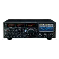
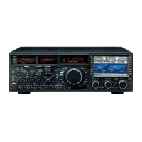
| Type | HF/50 MHz Transceiver |
|---|---|
| Receiver Type | Triple conversion superheterodyne |
| IF DSP | Yes |
| Display | LCD |
| Antenna Connectors | SO-239 |
| Modes | SSB, CW, AM, FM, RTTY, PSK31 |
| RF Output Power | 200 W |
| Image Rejection | 80 dB |
| IF Rejection | 80 dB |
| Supply Voltage | 13.8 V |
| Weight | 15 kg |
| IF Frequency | 69.450 MHz |
| Power Supply | External |
| Frequency Range | 160m to 6m |