EasyManua.ls Logo

Yaesu FTV-1000 - User Manual

Yaesu FTV-1000
16 pages
Print Icon
To Next Page IconTo Next Page
Loading...
FTV-1000 Operating Manual
50MHz Transverter
FTV-1000
Operating Manual
VERTEX STANDARD CO., LTD.
4-8-8 Nakameguro, Meguro-Ku, Tokyo 153-8644, Japan
VERTEX STANDARD
US Headquarters
10900 Walker Street, Cypress, CA 90630, U.S.A.
YAESU EUROPE B.V.
P.O. Box 75525, 1118 ZN Schiphol, The Netherlands
YAESU UK LTD.
Unit 12, Sun Valley Business Park, Winnall Close
Winchester, Hampshire, SO23 0LB, U.K.
VERTEX STANDARD HK LTD.
Unit 5, 20/F., Seaview Centre, 139-141 Hoi Bun Road,
Kwun Tong, Kowloon, Hong Kong
Question and Answer IconNeed help?

Do you have a question about the Yaesu FTV-1000 and is the answer not in the manual?

Overview

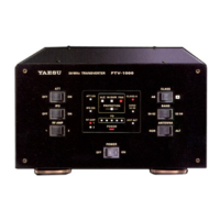
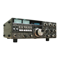
The Yaesu FTV-1000 is a high-performance 50MHz Transverter designed for use with the Yaesu MARK-V FT-1000MP transceiver. It extends the operating capabilities of the FT-1000MP to the 50-54 MHz band, providing excellent receiver performance and up to 200 Watts of power output. This transverter is specifically engineered to meet the demanding requirements of 50 MHz DX operators.

Function Description:

The FTV-1000 acts as an interface between the MARK-V FT-1000MP transceiver and a 50 MHz antenna system. It converts the 28-30 MHz IF (Intermediate Frequency) output from the FT-1000MP to the 50-54 MHz band for transmission, and conversely, converts received 50-54 MHz signals back to the 28-30 MHz IF for the FT-1000MP. This allows the FT-1000MP, which natively operates on HF bands, to function on the 6-meter band.

Important Technical Specifications:

  • Frequency Range: 50 - 54 MHz
  • I.F. (Input/Output): 28 - 30 MHz
  • TX Drive Level: 50 mVrms (-13 dBm)
  • TX Power Output: 200 Watts (Class A: 50 W)
  • Antenna Impedance: 50 Ohms nominal
  • Spurious Emissions: -60 dB or better
  • Power Requirements: +30 V and +13.8 V DC
  • Power Consumption (approx.):
    • Rx (no signal): 0.5 A (13.8 VDC), 0.5 A (30 VDC)
    • Tx (200 W): 0.5 A (13.8 VDC), 14.5 A (30 VDC)
  • Dimensions (WxHxD): 9.8" x 5.4" x 13" (248 x 136 x 332 mm)
  • Weight (approx.): 16.5 lb (7.5 kg)

Usage Features:

The FTV-1000 offers a comprehensive set of features for optimized 50 MHz operation:

  • POWER Switch: This is the main ON/OFF switch for the FTV-1000. When the FTV-1000 is turned on, the PA section of the MARK-V FT-1000MP is automatically disabled to prevent simultaneous full power output on 28 MHz.
  • ATT Switch: This switch engages a 12 dB receiver front-end attenuator, useful for reducing strong signals and noise during local communications. It should be disengaged for weak signal reception.
  • IPO Switch (Intercept Point Optimization): This feature allows optimization of receiver front-end overload characteristics. Selecting IPO bypasses the front-end RF amplifier, feeding received signals directly to the first mixer, which is beneficial in strong-signal or noisy environments.
  • RF AMP Switch: This switch selects between two receiver front-end preamplifier configurations:
    • Preamplifier 1: Offers "Very Good" noise figure and "Excellent" IMD rejection.
    • Preamplifier 2: Provides "Excellent" noise figure and "Very Good" IMD rejection. This allows the operator to choose the best preamplifier for the prevailing background noise and signal conditions.
  • CLASS Switch (Class-A Operation): This switch changes the final amplifier operating mode to Class-A. In Class-A mode, the maximum output power is reduced to approximately 50 watts, but it yields an ultra-clean SSB signal waveform with 5th-order intermodulation (IMD) typically suppressed by at least 65 dB. This is a key feature for demanding DX operations where signal purity is paramount.
  • BAND Switch: This switch selects the 50 MHz amateur band segment:
    • "50-52" position: Operates in the 50 MHz ~ 52 MHz segment.
    • "52-54" position: Operates in the 52 MHz ~ 54 MHz segment.
    • Frequency conversion to the 28-30 MHz range is maintained for compatibility with the MARK-V FT-1000MP.
  • ANTENNA Switch: This switch allows selection between the NOR (Normal) or ALT (Alternate) antenna jacks on the rear panel, providing convenient antenna switching.
  • Display Indicators: The front panel includes various LED indicators to show the operating status:
    • ATT ON: Red indicator for engaged receiver attenuator.
    • IPO ON: Red indicator for bypassed front-end RF amplifier.
    • RF AMP 1/2: Red indicators for selected preamplifier.
    • ALC: Red indicator for abnormally high ALC voltage.
    • HI SWR: Red indicator for abnormally high SWR.
    • FAN: Red indicator when the cooling fan is active (normal operation).
    • PROTECTION: Red indicator for abnormally high power amplifier temperature.
    • CLASS-A: Red indicator for Class-A operating mode.
    • BAND 52-54: Red indicator for 52-54 MHz band segment (off for 50-52 MHz).
    • PO meter: Five LEDs indicating RF power output (all illuminated at 200 watts).
    • ANT ALT: Red indicator for selected ALT antenna jack.
    • POWER: Red indicator when the FTV-1000 is turned on.
  • Rear Panel Connectors:
    • TRANSCEIVER Jack: Connects to the ANT jack of the MARK-V FT-1000MP.
    • ANT ALT/NOR Jacks: M-type (SO-239) connectors for 50 MHz antennas (ALT) and HF/50 MHz antennas (NOR).
    • DC POWER IN/OUT Jacks: For connecting to the FP-29 AC power supply and providing DC voltages to the MARK-V FT-1000MP.
    • GND Terminal: For connecting to an earth ground.
    • BAND DATA Jack: 8-pin DIN jack for control cable connection to the MARK-V FT-1000MP.
    • LIN BAND DATA Jack: 8-pin DIN jack for control signals to the VL-1000 Linear Amplifier.
    • ALC SET Potentiometer: For adjusting the maximum output power of the FTV-1000.
    • LIN ALC Jack: RCA jack for ALC voltage input from the VL-1000 Linear Amplifier.
    • ALC Jack: RCA jack for ALC (output) voltage to control the MARK-V FT-1000MP's drive level (0 to -4 VDC).
    • TX IN Jack: RCA jack for connection to the TRV jack of the MARK-V FT-1000MP (optimum drive level: approx. 50 mVrms at 50 Ω).
    • ATT Switch (Rear Panel): Activates a 6 dB input RF power attenuator for excessive input power from an exciter. Normally set to "off" when used with the MARK-V FT-1000MP.

Maintenance Features:

The manual outlines proper interconnection procedures and provides pinout diagrams for the various connectors, which are crucial for correct setup and troubleshooting. The inclusion of a "PROTECTION" indicator helps in identifying potential overheating issues, prompting the user to take corrective action to prevent damage. The "FAN" indicator confirms the cooling system is active, which is part of normal operation and not necessarily an error state. The "HI SWR" indicator alerts the user to antenna system problems that could lead to damage if not addressed.

The FTV-1000 is designed for seamless integration with the Yaesu MARK-V FT-1000MP and the VL-1000 Quadra System Linear Amplifier, providing an unparalleled operating experience across 1.8 to 54 MHz, with a particular focus on high-performance 6-meter operation. The supplied cables (DC POWER, ANTENNA, BAND DATA, ALC, TRV) ensure proper connectivity and signal transfer between the components.

Yaesu FTV-1000 Specifications

General IconGeneral
BrandYaesu
ModelFTV-1000
CategoryTransceiver
LanguageEnglish

Related product manuals