EasyManua.ls Logo

Yaesu FT-102 User Manual

Yaesu FT-102
67 pages
To Next Page IconTo Next Page
Page #1 background imageLoading...
Page #1 background image
Message from:
Amateur Radio Station VA3VFO
Greg White, owner/operator
Re. Yaesu, Model 102 Series, Amateur Radio Equipment
Greetings from Toronto, Canada! I hope you will find the attached Yaesu manual
helpful. I have been assisted many times, by Hams whom have kindly made manuals
available for free via mail and the Internet. I would like to take this
opportunity to now make a contribution of my own.
I have noted the famous Yaesu Model 102 Series of radio equipment manuals absent
from the Internet. I am a happy owner of a complete Yaesu 102 station and in
possession of its manuals. Hearing of many requests for the manuals, I have
scanned my collection and present it to you here, free of charge. I do so with
the hope that it will assist you in keeping your own Yaesu 102 equipment running
forever and as correctly intended by the factory. I also realize how frustrating
it can be trying to remember the forgotten instructions of a destroyed or
misplaced manual!
I request that these files remain free for private distribution and personal use
by fellow licensed Amateur Radio Operators only and that they are to be
considered as if "on loan". No fees are to be charged for, or as a result of
their use, nor are they to be published publicly. They are provided for private
personal reference only and if shared with other Hams, I ask that the credit for
the scanning and free "loan" remain with me.
I look forward to your continued support of the excellent FT102 Transceiver and
Accessories and helping to build both its continued demand as a "collectable" and
its assured respect in Amateur Radio history.
73
yours truly,
Greg White
VA3VFO
Toronto, CANADA
va3vfo@rac.ca
Downloaded by
RadioAmateur.EU
Question and Answer IconNeed help?

Do you have a question about the Yaesu FT-102 and is the answer not in the manual?

Yaesu FT-102 Specifications

General IconGeneral
TypeHF Transceiver
Frequency Range1.8-29.99 MHz
ModesSSB, CW, AM
Power Output40W AM
Tuning Steps1 kHz
Receiver Sensitivity0.5 µV (SSB)
Selectivity2.4 kHz
Power SupplyAC 110/220 V

Summary

General Description

FT-102 HF All Mode Transceiver Overview

Provides a comprehensive overview of the FT-102's capabilities and design.

Specifications

Technical Specifications Summary

Details frequency coverage, operating modes, power requirements, and performance metrics.

Front Panel Controls and Switches

Front Panel Controls Overview (1-6)

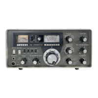
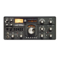
Describes the main controls and switches on the front panel of the FT-102.

Push Button Switches (7)

Explains the function of various push button switches for operation.

Miniature Knobs (8)

Details the functions of the six miniature knobs for adjustments.

Rear Panel Connectors and Controls

Rear Panel Connectors and Switches (1-3)

Details the various connectors and slide switches on the rear panel.

Interconnections

Interconnection Diagrams

Illustrates various connection setups for the FT-102 with accessories.

Installation

Power Connection Procedures

Instructions for connecting the transceiver to the AC power source.

Transceiver Location and Grounding

Guidance on proper placement and grounding for optimal performance.

Microphone Information

Operation

Receiver Operation Guide

Step-by-step guide for setting up and operating the receiver.

Transmitter Operation

Transmitter Tuning Procedure

Detailed steps for tuning the transmitter for proper output and purity.

SSB Operation Details

Instructions for setting up and operating in Single Sideband mode.

CW Operation Details

Instructions for setting up and operating in Continuous Wave mode.

AM Operation Details

Instructions for setting up and operating in Amplitude Modulation mode.

FM Operation Details

Instructions for setting up and operating in Frequency Modulation mode.

FT-102 Frequency Relationships

Maintenance & Alignment

Section I: Owner Adjustments

User-level adjustments not requiring specialized test equipment.

Final Amplifier Adjustments

Steps for bias adjustment, PO meter calibration, and neutralization.

Section II: Precision Alignment

Advanced alignment procedures requiring specialized test equipment.

Optional Crystal Filter Installation

AM/FM Unit Installation

Related product manuals