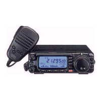
Do you have a question about the Yaesu FT-100D and is the answer not in the manual?
Lists accessories that are included with the transceiver.
Lists optional accessories that can be purchased for the transceiver.
Procedure for connecting the microphone and mounting the front panel.
Details on connecting the DC power supply and recommended supplies.
Guidelines for effective grounding for mobile and base station setups.
Information on antenna system requirements and impedance matching.
Safety information regarding RF energy exposure and FCC regulations.
Minimizing interference with computers and other electronic devices.
Ensuring proper airflow around the transceiver for longevity.
Procedures for connecting external accessories like linear amplifiers.
Connecting Terminal Node Controllers for digital modes like RTTY.
Connecting TNCs for FM packet operations.
Connecting straight keys and external electronic keyers for CW.
Instructions for connecting headphones via an adapter circuit.
How to tilt the transceiver for better viewing using the front feet.
Initial checks before operating the transceiver.
Key steps to get the transceiver operating quickly.
Procedure for powering the transceiver on and off.
How to switch between different amateur radio bands.
Selecting operating modes like SSB, CW, AM, and FM.
Adjusting the receiver's audio output volume.
How to set the desired operating frequency using main controls.
Using the FUNC key and other buttons to access features.
Understanding the icons shown on the transceiver's LCD.
Selecting appropriate IF filter bandwidths for different modes.
Adjusting tuning steps for frequency selection.
Changing the rate at which frequency changes with dial rotation.
Tuning in 1 MHz increments for general coverage.
Tuning in 10 MHz increments for VHF/UHF bands.
Using two VFOs on the same band for flexible operation.
Configuring programmable buttons on the microphone.
Disabling controls to prevent accidental changes.
Adjusting the LCD screen brightness level.
Adjusting receive frequency offset without changing transmit frequency.
Using sidetone for CW signal spotting.
Configuring the receiver's automatic gain control recovery time.
Reducing impulse noise using the IF noise blanker.
Setting the squelch threshold to mute background noise.
Bypassing the receiver preamplifier for improved strong-signal characteristics.
Using the front-end attenuator to reduce strong signals and noise.
Shifting the receiver's IF passband to reduce interference.
Adjusting CW sidetone pitch and filter center frequencies.
Using the reverse sideband for CW reception.
Adjusting high-cut and low-cut characteristics of the DSP filter.
Activating a narrow-bandwidth filter for crowded CW conditions.
Enhancing signal-to-noise ratio on weak signals using DSP NR.
Removing offending carrier or heterodyne signals from the audio.
Enabling the MAIN DIAL for tuning in AM and FM modes.
Setting the timer for automatic transceiver power-off.
Adjusting the maximum power output level for different bands.
Tailoring audio response using DSP for transmission.
Basic setup and operation for SSB mode.
Using voice activation for automatic transmit/receive switching.
Increasing power output with the AF speech processor.
Operating procedures for CW transmission modes.
Connecting and using straight keys or external keying devices.
Utilizing the transceiver's integrated electronic keyer.
Storing and playing back messages using the memory keyer.
Operating procedures for FM transmission modes.
Direct FM communication without using repeaters.
Setting the display to monitor SWR for antenna adjustments.
Configuring the transceiver for repeater access and operation.
Using CTCSS tones for repeater access and silent monitoring.
Using Digital Code Squelch for enhanced tone access control.
Sending DTMF tones for autopatch or repeater control.
Using ARTS for communication range monitoring.
Setting up the transceiver to send CW identification.
Operating on split frequencies for DX or unique contacts.
Setting a limit on continuous transmission duration.
Capabilities for digital mode communication.
Procedures for operating RTTY using AFSK.
Operating packet modes at different data rates.
Enabling and initiating automatic antenna tuning with ATAS-100.
Performing manual antenna adjustments for optimal SWR.
Tips for deriving best performance from the ATAS-100 antenna.
Importance of proper mechanical and RF ground connections for ATAS-100.
Guidance for operating the ATAS-100 on specified bands.
How the FC-20 stores impedance matching data for instant adjustment.
Storing and recalling frequencies using Quick Memory Bank channels.
Procedure for storing frequency data into QMB channels.
Recalling stored frequencies from QMB channels.
Storing and recalling data in the 300 standard memory channels.
Steps for storing frequency data into regular memory channels.
Recalling stored frequencies from regular memory channels.
Storing and recalling split frequencies for DX operations.
Procedure for storing split frequency data.
Recalling stored split frequencies.
Using special one-touch HOME channels for frequent frequencies.
Storing frequency data into HOME channels.
Recalling stored frequencies from HOME channels.
Accessories related to memory mode operations.
Transferring stored memory data to a VFO.
Procedure for deleting stored frequency data from a memory channel.
Fundamental scanning capabilities in VFO, Memory, and PMS modes.
Marking memory channels to be skipped during scanning.
Limiting scanning or tuning within specified frequency ranges.
Selecting how the scanner resumes after detecting a signal.
Monitoring two frequencies simultaneously by periodic switching.
Overview of the Menu System for transceiver customization.
Setting the speed of the MAIN DIAL knob for frequency tuning.
Selecting the desired scan-resume mode.
Setting the delay time for scanner resume.
Enabling/disabling CW identifier during ARTS operation.
Setting the CTCSS Tone frequency.
Selecting the sweep mode for the Spectrum Scope feature.
Setting the DSP microphone equalization pattern.
Adjusting the high-cut characteristics of the DSP LPF filter.
Setting the maximum power level for the HF band.
Setting the microphone gain level for SSB and AM modes.
Setting the compression level for the AF speech processor.
Selecting the Time-Out Timer duration.
Selecting the maximum deviation for FM operation.
Selecting the mode and sideband for AFSK operation.
Setting the repeater shift magnitude for the 28 MHz band.
Activating/deactivating Automatic Repeater Shift on 144 MHz band.
Selecting the keyer paddle operating mode.
Setting the pitch of the CW sidetone and filter frequencies.
Setting the gain of the VOX circuitry's input audio detector.
Selecting the operation of the SQL/RF knob.
Selecting the operation of the front panel's LOCK key.
Selecting tuner or ATAS-100 to be controlled via the TUN key.
Enabling Tx/Rx operation on the Alaska Emergency Channel.
Understanding the command structure and byte format for CAT control.
Examples of creating and sending CAT commands to the transceiver.
Reference chart for CAT command opcodes and their parameters.
Information about reading transceiver status updates via CAT commands.
Procedures for resetting the microprocessor to factory defaults.
Troubleshooting steps for when the transceiver does not power on.
Troubleshooting steps for lack of audio output.
Troubleshooting steps for weak audio with S-meter activity.
Troubleshooting steps for inability to transmit.
Troubleshooting specific issues related to FM mode operation.
Troubleshooting specific issues related to digital mode operations.
Troubleshooting for display or microprocessor malfunctions.
Troubleshooting CAT system data transfer issues.
Procedure for installing optional IF filters XF-117CN and XF-117A.
| Product type | Portable CB radio |
|---|---|
| Product color | Black |
| Housing material | - |
| Display type | LCD |
| Output power | 100 W |
| AM band range | 5.2 - 18 kHz |
| FM band range | 15 - 25 MHz |
| Frequency range | 0.1 - 961 MHz |
| Channels quantity | 50 channels |
| Compatible products | ATAS-120\\tActive-Tuning Antenna System FC-20\\tAutomatic Antenna Tuner YSK-100\\tSeparation Kit XF-117CN\\t300Hz CW Filter MH-36B6JS\\tDTMF Microphone FTS-27\\tCTCSS Tone Decoder Unit |
| Microphone included | Yes |
| Input voltage | 13.8 V |
| Depth | 205 mm |
|---|---|
| Width | 160 mm |
| Height | 54 mm |