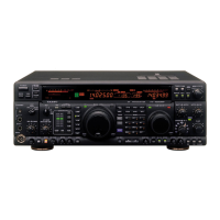
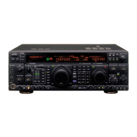
Do you have a question about the Yaesu Mark-V FT-1000MP and is the answer not in the manual?
Covers frequency ranges, stability, temperature, modes, impedance, and power.
Details power output, duty cycle, modulation types, and SSB specs.
Lists items included with the transceiver.
Describes optional accessories like TCXO, microphone, and filters.
Guidelines for connecting power supply and DC power.
Ensuring proper ground system for safety and performance.
Advice on preventing electrical shock hazards.
Steps for initial inspection of the transceiver and accessories.
Recommendations for optimal transceiver placement and ventilation.
Discusses antenna impedance, SWR, and coaxial cable selection.
Details connecting linear amplifiers for band switching and QSK.
Details connecting TNCs and computers for digital modes.
Provides configuration tips for CW keying interfaces.
Describes the function of the power button.
Explains MOX and VOX modes for transmitter activation.
Details Automatic Gain Control decay time settings.
Sets audio level for the sub receiver to headphone jack A.
Sets audio level for the main receiver to headphone jack A.
Adjusts tuning meter segment indications.
Connects main antennas for transmission and reception.
Connects a remote control keypad for transceiver functions.
Accepts CW key or keyer paddle input.
Initial setup procedures and control presets before operation.
Explains the menu system for customizing transceiver functions.
General overview of receiving operations.
How to select operating modes like SSB, CW, RTTY, PKT.
How to select VFOs and mute receiver channels.
Explains the tuning meter displays for CW, RTTY, and Packet.
How to use the narrow band-pass preselector filter.
Optimizing front-end gain, IPO, and attenuator settings.
Selecting AGC decay time for different modes and conditions.
Activating and selecting IF noise blanker types.
Selecting 2nd and 3rd IF filters for receiver bandwidth.
Narrowing passband skirts to reduce QRM.
Tuning the receiver IF passband relative to the displayed frequency.
Using the notch filter to null heterodyne interference.
Offsetting receive or transmit frequencies for split operation.
How to select between connected antennas.
Using the built-in antenna tuner for impedance matching.
Steps for transmitting in LSB or USB modes.
Activating and adjusting the RF speech processor.
Enabling Class-A mode for ultra-linear SSB transmission.
Setting up VOX for automatic transmit/receive switching.
Using the built-in electronic keyer modes.
Improving CW sending quality with automatic character spacing.
Setting CW pitch and using the spotting oscillator.
Setup for AM transmission, including modulation and power limits.
Overview of connecting to digital mode devices.
Details on setting up and operating RTTY.
Connecting and operating 300-baud packet data.
Setup for FM transmission on 29 MHz.
Features for operating on FM repeaters, including shift and CTCSS.
Explains controlling the Sub VFO and its features.
How to activate and use dual receive capabilities.
Receiving signals on opposite sidebands for AM signals.
Storing frequencies and settings into memory channels.
Transferring VFO settings to a memory channel.
Selecting and operating from stored memory channels.
Initiating VFO scan for activity.
Scanning through stored memory channels.
Configuring how scanning pauses or stops on detected activity.
Overview of Enhanced Digital Signal Processing capabilities.
Explains EDSP's digital signal processing for audio enhancement.
Automatically matching EDSP Contour filter to IF bandwidth.
Overview of using the FH-1 Remote Control Keypad.
Features for contest memory keying and message storage.
Using the keypad for VFO and memory control.
Recalling pre-configured operating environments (mode, filters, offsets).
Describes the DVS-2 digital voice recorder for recording/playback.
Connecting the DVS-2 unit to the transceiver.
Recording received signals for later playback.
Explains linking the transceiver to a telephone line.
Calibrating the CW tuning meter after changing CW Pitch.
Calibrating the RTTY tuning meter after changing RTTY shift.
Calibrating the Packet tuning meter after changing packet tones.
Describes the CAT system for computer control of the transceiver.
Explains the serial data structure and communication protocol.
How to build and send CAT commands.
How to download transceiver operational data via CAT.
Structure of transceiver status data returned via CAT.
Format for memory channel number data in CAT commands.
Structure of 16-byte data records for VFO and memory settings.
Provides BASIC coding examples for CAT command functions.
Table listing CAT opcodes and their parameters.
Overview of menu selections for transceiver configuration.
Lists the available menu items and their functions.
Configures memory channel groups for organization.
Allocates channels for the instant-write quick-memory feature.
Automatically increments memory channel selection during VFO programming.
Enables or disables the EDSP feature for audio enhancement.
Adjusts tuning speed for VFO dials and controls.
Selects tuning step size for IF SHIFT/WIDTH controls.
Sets the tuning step size for the Main VFO-A.
Selects SSB filters for the front-panel [NOR] switch.
Selects CW filters used when the [NOR] switch is selected.
Selects standard or custom frequency shift for RTTY.
Selects the keyer emulation mode (Iambic 1, BUG, Iambic 2).
Adjusts the dot character weight for CW keying.
Adjusts the dash character weight for CW keying.
Selects FAST button actuation mode (Momentary/Continuous).
Configures the panel 'Lock' mode (Dial, Panel, Primary).
Selects one of three split operating modes (Normal, Auto, A=B).
Configures a custom operating environment for specific modes.
Selects AGC recovery time for the Sub receiver.
Enables or disables the internal automatic antenna tuner.
Table showing frequency and offset settings for various modes.
Further table of selected filter offsets according to mode.
Lists default USER mode settings for various configurations.
Table of pre-configured settings for SSTV, FAX, PSK-31 modes.
Describes the Temperature-Compensated Crystal Oscillator option.
Step-by-step guide for installing the TCXO-6 unit.
Installation of optional crystal IF filter units.
Installation of the optional Collins mechanical filter.
Procedure for replacing the transceiver's internal lithium battery.
Steps for replacing the internal 13.8V fuse.
Explains the function of the rear panel memory backup switch.
Procedures for resetting transceiver settings to factory defaults.
| Modes | SSB, CW, AM, FM, FSK |
|---|---|
| Receiver Type | Triple Conversion Superheterodyne |
| Audio Output | 2.5 W into 4 ohms |
| Antenna Impedance | 50 ohms |
| Receiver Sensitivity | 0.16 μV for 10 dB S/N |
| Image Rejection | 70 dB |
| IF Bandwidth | 500 Hz (CW) |
| Power Supply Requirement | 13.8 VDC ±10% |
| IF Rejection | >70 dB |




 Loading...