EasyManua.ls Logo

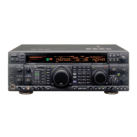
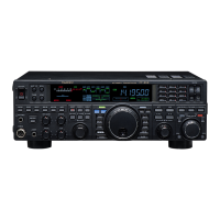
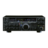
Yaesu Mark-V FT-1000MP Field User Manual

Yaesu Mark-V FT-1000MP Field
211 pages
To Next Page IconTo Next Page
Page #1 background imageLoading...
Page #1 background image
© 2002 VERTEX STANDARD CO., LTD. EH013H90A
Technical Supplement
HF Transceiver
This manual provides technical information necessary for servicing the Yaesu MARK-V
FT-1000MP
Field HF transceiver. It does
not include information on installation and operation, which are described in the MARK-V
FT-1000MP
Field Operating Manual, pro-
vided with each transceiver, or on MARK-V
FT-1000MP
Field accessories, which are described in manuals provided with each.
The MARK-V
FT-1000MP
Field is carefully designed to allow the knowledgeable operator to make nearly all adjustments required
for various station conditions, modes and operator preferences simply from the controls on the panels, without opening the case of the
transceiver. The MARK-V
FT-1000MP
Field Operating Manual describes these adjustments, plus certain internal settings.
Servicing this equipment requires expertise in handling surface mount chip components. Attempts by non-qualified persons to service
this equipment may result in permanent damage not covered by warranty. For the major circuit boards, each side of the board is identified
by the type of the majority of components installed on that side. In most cases one side has only chip components, and the other has either
a mixture of both chip and lead components (trimmers, coils, electrolytic capacitors, packaged ICs, etc.), or lead components only.
While we believe the technical information in this manual is correct, Vertex Standard assumes no liability for damage that may occur
as a result of typographical or other errors that may be present. Your cooperation in pointing out any inconsistencies in the technical
information would be appreciated. Vertex Standard reserves the right to make changes in this transceiver and the alignment procedures, in
the interest of technological improvement, without notification of the owners.
VERTEX STANDARD CO., LTD.
4-8-8 Nakameguro, Meguro-Ku, Tokyo 153-8644, Japan
VERTEX STANDARD
US Headquarters
17210 Edwards Rd., Cerritos, CA 90703, U.S.A.
International Division
8350 N.W. 52nd Terrace, Suite 201, Miami, FL 33166, U.S.A.
YAESU EUROPE B.V.
P.O. Box 75525, 1118 ZN Schiphol, The Netherlands
YAESU UK LTD.
Unit 12, Sun Valley Business Park, Winnall Close
Winchester, Hampshire, SO23 0LB, U.K.
VERTEX STANDARD HK LTD.
Unit 5, 20/F., Seaview Centre, 139-141 Hoi Bun Road,
Kwun Tong, Kowloon, Hong Kong

Table of Contents

Question and Answer IconNeed help?

Do you have a question about the Yaesu Mark-V FT-1000MP Field and is the answer not in the manual?

Yaesu Mark-V FT-1000MP Field Specifications

General IconGeneral
Frequency Range RX100 kHz - 30 MHz
Receiver TypeDouble conversion superheterodyne
Antenna Impedance50 ohms
Weight15 kg
Voltage13.8 VDC
ModesAM, FM, SSB, CW, FSK
Current Drain TX22 A
Receiver Sensitivity0.16 μV (SSB, CW)
Frequency Range TX160, 80, 40, 30, 20, 17, 15, 12, 10 m

Summary

Specifications

General Specifications

General operating parameters including frequency range, stability, and modes.

Transmitter Specifications

Transmitter specifications detailing power output, duty cycle, and modulation types.

Receiver Specifications

Receiver specifications including circuit type, sensitivity, and selectivity.

Exploded View & Miscellaneous Parts

Alignment Procedures

Alignment Introduction and Precautions

Important safety and procedural notes for performing transceiver alignment.

Alignment Preparation & Precautions

Required test equipment and environmental conditions for correct alignment.

REF Unit Alignment

Procedure for confirming the carrier frequency of the REF Unit.

RX2 Unit Alignment

Procedures for aligning the RX2 Unit's local section and PLL.

Local Unit Alignment

Alignment steps for the Local Unit's oscillators and DDS amplifier.

PA Unit Alignment

Procedures for setting PA unit idling current for Class AB and A modes.

Transmitter Section Alignment

Steps for aligning transmitter mixer, IF transformers, ALC, power output, and TX IF gain.

Tuning Meter Presets

Procedures for setting tuning meter center and presets for various modes.

Circuit Description

Main Receive Signal Circuitry

Description of the receive signal path from antenna to IF stages.

AGC Circuit

Explanation of the Automatic Gain Control circuit operation.

Low-Frequency Amplifier Circuit

Description of the low-frequency amplifier stages and audio output.

Transmit Signal Circuitry

Description of the signal path from microphone to RF output for FM, SSB transmission.

ALC Circuit

Explanation of the ALC circuit for automatic level control.

Control Circuitry

Description of microprocessor, EEPROM, reset, dial counter, serial comms, CAT, key matrix, and ADC circuitry.

PLL Frequency Synthesizer (Main)

Details on master oscillator, DDS units, local oscillators, and PLL circuit operation.

RX2 Circuit

Description of receive signal flow, AGC operation, and RX2 PLL synthesizer.

DSP Circuit

Description of DSP for transmission system including AD/DA converters and processor functions.

Block Diagram

Interconnection Diagram

Wire List

Related product manuals