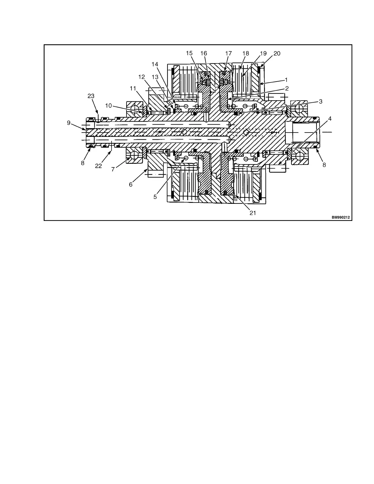
1. END PLATE
2. PISTON
3. O-RING
4. FORWARD GEAR
5. RETURNING SPRING
6. REVERSING GEAR
7. BEARING
8. SEAL RING (A)
9. INPUT SHAFT ASSEMBLY
10. THRUST COLLAR (A)
11. NEEDLE BEARING
12. THRUST SHAFT COLLAR (B)
13. AXIS SNAP RING
14. SPRING SEAT
15. STEEL BALL
16. PLUG
17. SEAL RING (B)
18. SPACER
19. BRAKE SHOE
20. STOPPER
21. DISC PLATE
22. FORWARD OIL CIRCUIT
23. REVERSE OIL CIRCUIT
Figure 9. Forward/Reverse Clutch Pack
CONTROL VALVE, SAFETY VALVE, AND
INCHING VALVE
The Control Valve is mounted on the inner side of the
transmission case cover (see Figure 10). The control
valve includes three components: controlling slide
valve, constant pressure valve, and adjusting valve.
•
Controlling Slide Valve: Used to control
forward and backward functions.
•
Constant Pressure Valve: Maintains the oil
pressure of the hydraulic clutch to be within the
range of 1.1-1.4 MPa (159.5-203.1 psi).
•
Adjusting Valve: It is located between inching
valve and controlling slide valve. When
controlling slide valve is fully open, this valve
will start adjusting to reduce the impact of clutch
during engagement.
The Overflow Valve: The overflow valve is connected
to the transmission case and allows the oil pressure
from the torque converter to maintain within its
operating range 0.5-0.7 MPa (72.5-101.5 psi). See
Figure 16
The Inching Valve The inching valve is installed on
the left side of transmission case. The spool is
connected to the linking rod of the inching pedal. This
spool will move forward when inching pedal is
pressed. The oil pressure of the hydraulic clutch will be
reduced, causing the truck to move slowly. See
Figure 11.
8000 YRM 2199 Hydraulic Transmission Case and Torque Converter
13
 Loading...