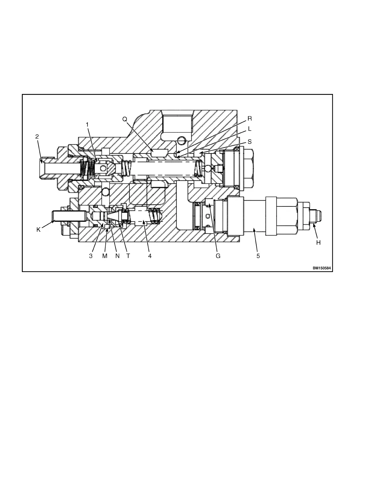
core (N) moves right, and pressure oil is connected
with low-pressure oil circuit through cavity (T), for the
pressure in cavity (M) to lower, in order to ensure the
stability for the pressure of steering system. Adjusting
screw K may be used to adjust the stable pressure
value of the system.
By changing the flow rate and pressure, the slide valve
L moves to the left and right to change the opening of
(R) and (S), to ensure the automatic balance of the
flow rate of the deworking chamber (Q) and PF orifice
and the full hydraulic steering gear, and the flow is
divided stable in proportion
1. ONE WAY VALVE
2. CONNECTING ORBITROL
3. STEERING OVERFLOW VALVE
4. OIL RETURN
5. MAIN RELIEF VALVE
Figure 41. Primary Relief Valve and Priority Spool
Inclined Auto-Lock Valve
The tilt spool valve is fitted with an auto-lock valve to
prevent vibration caused by back pressure inside the
tilt cylinder. It is designed to keep the mast of the lift
truck from "drifting" while a load is raised. The inclined
spool valve can still be operated to tilt backward after
the engine is turned off. However, when this tilt auto-
lock valve is used, a forward tilt can not be performed
when the engine is turned off. See Figure 42 for tilt
auto-lock valve structure.
Hydraulic System 8000 YRM 2199
44