Overhead Guard Replacement
REMOVE
WARNING
DO NOT operate the lift truck without the over-
head guard correctly fastened to the lift truck.
WARNING
DO NOT weld mounts for lights or accessories to
legs of the overhead guard. Changes that are
made by welding, or by drilling holes that are too
big or in the wrong location, can reduce the
strength of the overhead guard.
See your dealer for Yale lift trucks BEFORE per-
forming any changes to the overhead guard.
NOTE: The lift trucks covered in this YRM are equip-
ped with either a high or low overhead guard. The re-
moval and installation procedures for both types of
overhead guards are the same.
No welding or drilling on legs of overhead guard is
permitted as per previous WARNING.
NOTE: The lifting device can be connected to any
number of positions on overhead guard depending
upon lifting device available. The ideal choices are a
four point sling connected to all four corners on top of
overhead guard, or a two point sling connected to two
opposite corners of overhead guard. If a single point
hoist is used, make sure that lift point is in center of
overhead guard. If during initial start of lift, the over-
head guard is off balance, lower immediately and
move hoist to a more centered point.
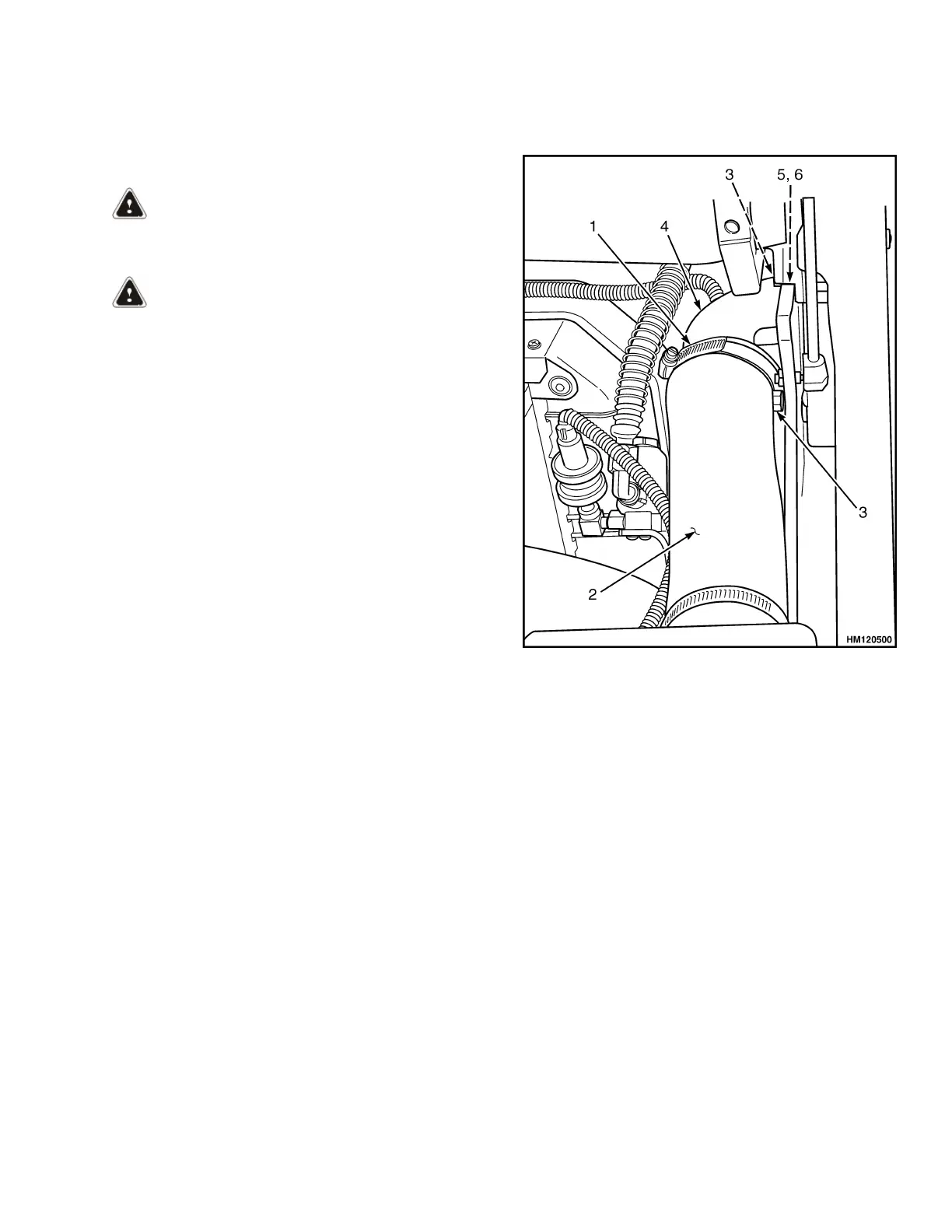
1. Connect a lifting device to remove overhead
guard. Loosen clamp and disconnect air intake
hose from elbow. Remove bolts, elbow, retainer,
and grommet from overhead guard rear leg. See
Figure 20.
2. Disconnect wires between frame and overhead
guard. When overhead guard is lifted from frame,
make sure that electrical wires are moved through
holes in overhead guard so that they are not dam-
aged.
3. The rear legs of overhead guard have two cap-
screws that are located under hood inside engine
compartment, next to radiator. Remove cap-
screws. See Figure 21.
1. CLAMP
2. AIR INTAKE HOSE
3. BOLTS
4. ELBOW
5. RETAINER
6. GROMMET
Figure 20. Disconnect Air Intake Hose
4. Remove fender cover, dash, and kick panel to re-
move two capscrews on front legs of overhead
guard. See Hood, Seat, and Side Covers Re-
placement for removal procedures.
5. Using a lifting device, remove overhead guard
from frame and place on floor.
INSTALL
1. Connect lifting device to top of overhead guard.
Install overhead guard in position on lift truck.
2. Install two capscrews on front legs of overhead
guard. Tighten capscrews to 66 N•m (49 lbf ft).
See Figure 21.
3. Install fender cover, dash, and kick panel. See
Hood, Seat, and Side Covers Replacement for in-
stallation procedures.
0100 YRM 1243 Overhead Guard Replacement
25