Table 22. Proc_Cal_025: Hydraulic Valve Pressure Gage Installation (Continued)
Information: "Creep" is defined as the threshold when a function first starts to move very slowly (barely percepti-
ble motion). The identification of this motion is defined as the "visual method." The method that provides more
consistent calibration is by monitoring the change in pressure when the function is activated; this is defined as
the "pressure method."
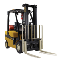
Action: With the ignition turned OFF, install a 24 MPa (3500 psi) minimum analog pressure gage in the EF Port.
(See illustration above.) It is highly recommended to use a small diameter hose (approximately 2 to 3 mm ID) to
minimize pressure variation seen at the gage.
Information: It is recommended that the diagnostic fitting installed in the EF Port is used. This fitting is a Parker
EMA3/3/7/16-20UNF-2A or HYDAC 06003735. A gage can be connected to this fitting by using a flexible hose
(Parker SMA3-200, SMA3-400, SMA3-800, SMA3-2000, SMA3-4000, or equivalent). The alternative is to re-
move the diagnostic fitting and connect directly to the EF Port; port size: SAE #4 O-ring Port (7/16-20UNF). If
this is done, ensure that the fitting is tightened to the torque specified per HC-712, and that the connection is
leak-free after the calibrations are completed and the gage is removed. Preceding procedure is the same for lift
trucks equipped with OPS solenoids.
Proc_Cal_026: Travel Speed Calibration
WHEN TO PERFORM
For trucks with electronic or enhanced electronic
transmissions that perform advanced functions, per-
form the calibration process whenever changing the
drive tire size or if the truck travel speed diagnostic
display is not reading correctly.
CALIBRATION ORDER
No prior calibration required.
WHY PERFORM
Advanced function transmission control decisions are
based on travel speed. The VSM needs accurate
travel speed information for advanced functions such
as enhanced power reversals, auto-decel, and travel
speed limiting, to work correctly.
HOW TO PERFORM
WARNING
Keep yourself and all others clear of the lift mech-
anism. Never allow anyone under or on the forks.
Never put hands, arms, head, or legs through the
mast or near the carriage or lift chains. This warn-
ing applies not only to the operator but also the
helper. A helper must not be near the load or the
lift mechanism while the operator is attempting to
handle a load. The lift mechanism has moving
parts with close clearances that can cause seri-
ous injury.
Refer to Table 23 for the procedures on how to per-
form Proc_Cal_026: Travel Speed Calibration.
8000 YRM 1134 Proc_Cal_025: Hydraulic Valve Pressure Gage Installation
Confidential/Proprietary - Do Not Copy or Duplicate 55