4
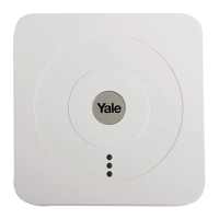
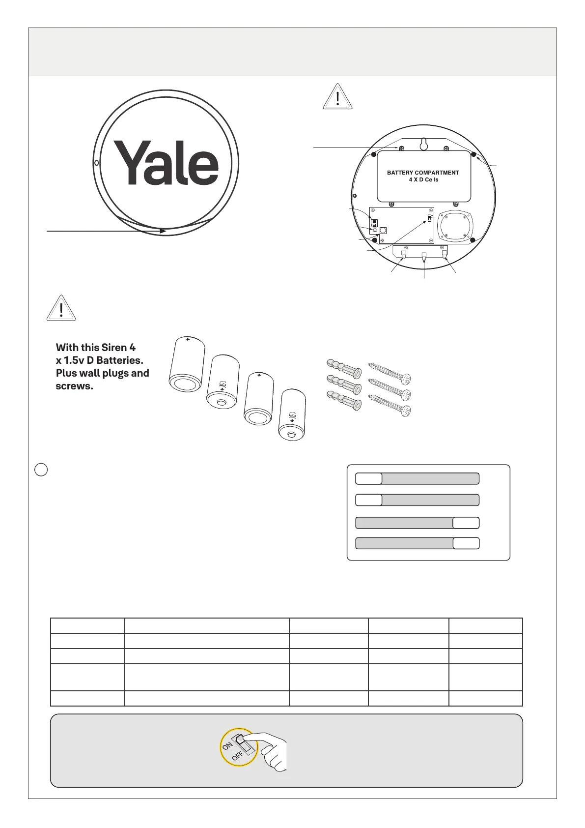
2. Overview of Alarm Components - The Siren
Programming
dip switches
Learn button
Tamper switch
Power switch
4 x Siren
fixing
screws
LED 1
LED 2
LED 3
Battery
compartment
screws x 4
Unscrew to
open battery
compartment
to remove
battery saver
tab before
first use.
Siren x 1
PIR Motion
Detector x 2
Door & Window Sensor x 2
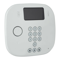
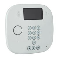
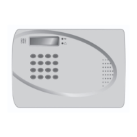
Keypad & Bracket x 1
Fixings
Instruction
Manual
Instruction
Manual
Dip switch positions:
Remove the cover by unscrewing the single screw
located on the left hand side. On the middle left
hand side you can see the programming dip switch
set, which consists of 4 small switches.
Function On Off Positions
Dip Switch 1 Clear Memory Clear Normal OFF
Dip Switch 2 Interference/Jamming detection Interference on Interference off OFF
Dip Switch 3 Set full arm/part arm attributes for
accessories when ‘learning in’
Full arm mode
(Entry)
Part arm mode
(Home Omit)
ON
Dip Switch 4 Stand Alone/Slave mode Stand alone Slave ON
With this Siren 4
x 1.5v D Batteries.
Plus wall plugs and
screws.
Shows as blue flashing
light when activated
The Siren is very loud! Take care not
to activate the Siren tamper switch
unnecessarily.
The Siren is the heart of the system. All components must be recognised by the Siren.
The function of each dip switch is listed below:
Before initial set up of the Alarm Kit begins, the dip switches should be set as shown in the diagram.
You do not need to change the setting of these dip switches unless mentioned in specific sections of this
manual.
Once battery saver tab has
been removed and battery
cover replaced, the Siren can
be powered on.
i
4
3
2
1
ON
OFF
1

 Loading...