30
O1X
PIN
NO.
I/O FUNCTIONNAME
PIN
NO.
I/O FUNCTIONNAME
1
2
3
4
5
6
7
8
9
10
11
12
13
14
15
16
17
18
19
20
21
22
23
24
25
26
27
28
29
30
31
32
RA1
RB1
RA2
RB2
V
SS
RA3
RB3
RA4
RB4
V
SS
RA5
RB5
RA6
RB6
V
SS
RA7
RB7
RA8
RB8
A0
A1
A2
V
SS
RDN
CSN
V
DD
ASN
A3N
SEL
NC
NC
NC
I
I
I
I
I
I
I
I
I
I
I
I
I
I
I
I
I
I
I
I
I
I
I
I
Encoder input
Ground
Encoder input
Ground
Encoder input
Ground
Encoder input
Address bus
Ground
Read
Chip select
Power supply +5V
Address strobe
Address bus
Bus select
Not used
33
34
35
36
37
38
39
40
41
42
43
44
45
46
47
48
49
50
51
52
53
54
55
56
57
58
59
60
61
62
63
64
D0
D1
V
SS
D2
D3
V
SS
D4
D5
V
SS
D6
D7
V
SS
NC
NC
RA9
RB9
RA10
RB10
RA11
RB11
RA12
RB12
RA13
RB13
RA14
V
DD
RB14
RA15
RB15
RA16
RB16
V
SS
O
O
O
O
O
O
O
O
I
I
I
I
I
I
I
I
I
I
I
I
I
I
I
I
Data bus
Ground
Data bus
Ground
Data bus
Ground
Data bus
Ground
Not used
Encoder input
Power supply +5V
Encoder input
Ground
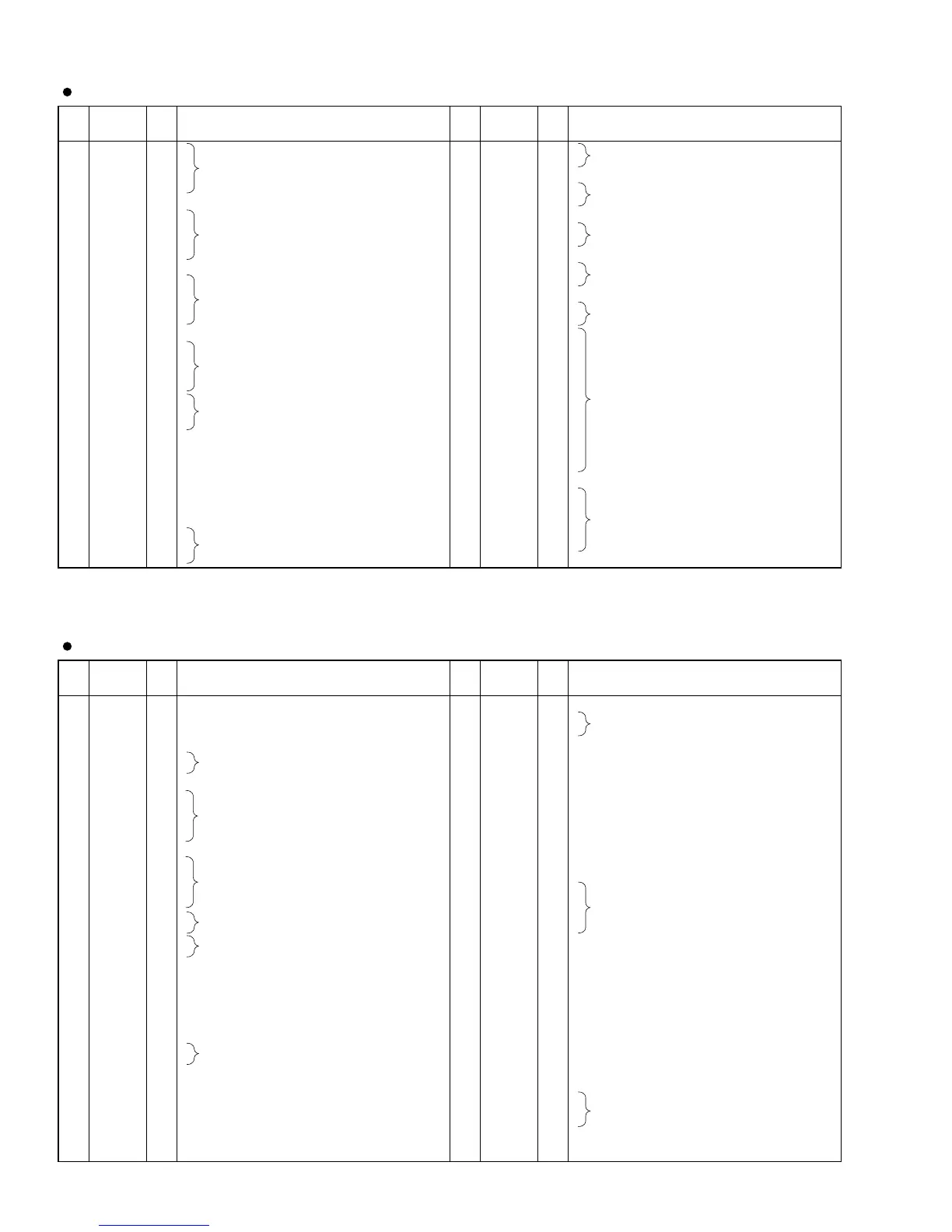
SGH603064F-62F (XV973A00) REC2 (Gate Array)
DM: IC402
PIN
NO.
I/O FUNCTIONNAME
PIN
NO.
I/O FUNCTIONNAME
1
2
3
4
5
6
7
8
9
10
11
12
13
14
15
16
17
18
19
20
21
22
23
24
25
26
27
28
29
30
31
32
33
34
LREQ
DVDD
SCLK
DVSS
CTL0
CTL1
DVDD
D0
D1
D2
D3
DVSS
D4
D5
D6
D7
DVDD
DVDD
TEST0
TEST1
DVSS
DVDD
DVSS
Purb
AGND
NC
NC
AVDD1
XEXT
XTAL
AGND
AVDD1
CPS
AGND
I
-
O
-
I/O
I/O
-
I/O
I/O
I/O
I/O
-
I/O
I/O
I/O
I/O
-
-
I
I
-
-
-
I
-
-
-
-
I/O
I/O
-
-
I
-
Link request
Digital power supply
49.152MHz link system clock
Digital ground
PHY-Link interface control signals
Digital power supply
PHY-Link interface data signals
Digital ground
PHY-Link interface data signals
Digital power supply
Test mode control terminals
Digital ground
Digital power supply
Digital ground
External capacitor connection terminal for
power-up reset
Analog ground
Non connection
Analog power supply 1
For crystal connections. Connection
terminals for quartz crystal oscillators.
Analog ground.
Analog power supply 1
A terminal for Cable Power Status detection
Analog ground
35
36
37
38
39
40
41
42
43
44
45
46
47
48
49
50
51
52
53
54
55
56
57
58
59
60
61
62
63
64
AVDD1
TpBias1
TpBias0
TpB1n
TpB1p
TpA1n
TpA1p
TpB0n
TpB0p
TpA0n
TpA0p
AGND
AVDD2
DVSS
Disabled1
Disabled0
S200
LDSEL
DVDD
En_Accel
En_Multi
SR
DIRECT
DVSS
LinkOn
PC2
PC1
PC0
CMC
LPS
-
O
O
I/O
I/O
I/O
I/O
I/O
I/O
I/O
I/O
-
-
-
I
I
I
I
-
I
I
I
I
-
O
I
I
I
I
I
Analog power supply 1
A cable bias output terminal
A negative-phase-sequence I/O terminal
A positive-phase-sequence I/O terminal
A negative-phase-sequence I/O terminal
A positive-phase-sequence I/O terminal
A negative-phase-sequence I/O terminal
A positive-phase-sequence I/O terminal
A negative-phase-sequence I/O terminal
A positive-phase-sequence I/O terminal
Analog ground
Analog power supply 2
Digital ground
These pin define the initial value of the disable bits in the
PHY port status page after a hardware reset, and the
condition of the terminal of the level is reflected.
Phy Speed Control signal
Timing setting terminal for the PHY-Link interface
Digital power supply
This bit defines the initial value of the
Enab_accel bit after a hardware reset
This bit defines the initial value of the
Enab_multi bit after hardware reset
Suspend/Resume function control signal
Defines operation mode setting terminal for
the PHY-Link interface
Digital ground
Link-On signal output
Power Class
Configuration management capable setting terminal
Link power status
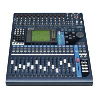
MD8408B (XZ762A00) PHY (Physical Layer)
MLN2: IC010