13
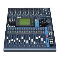
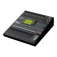
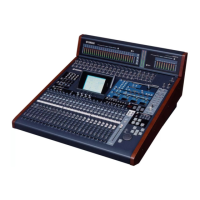
O1X
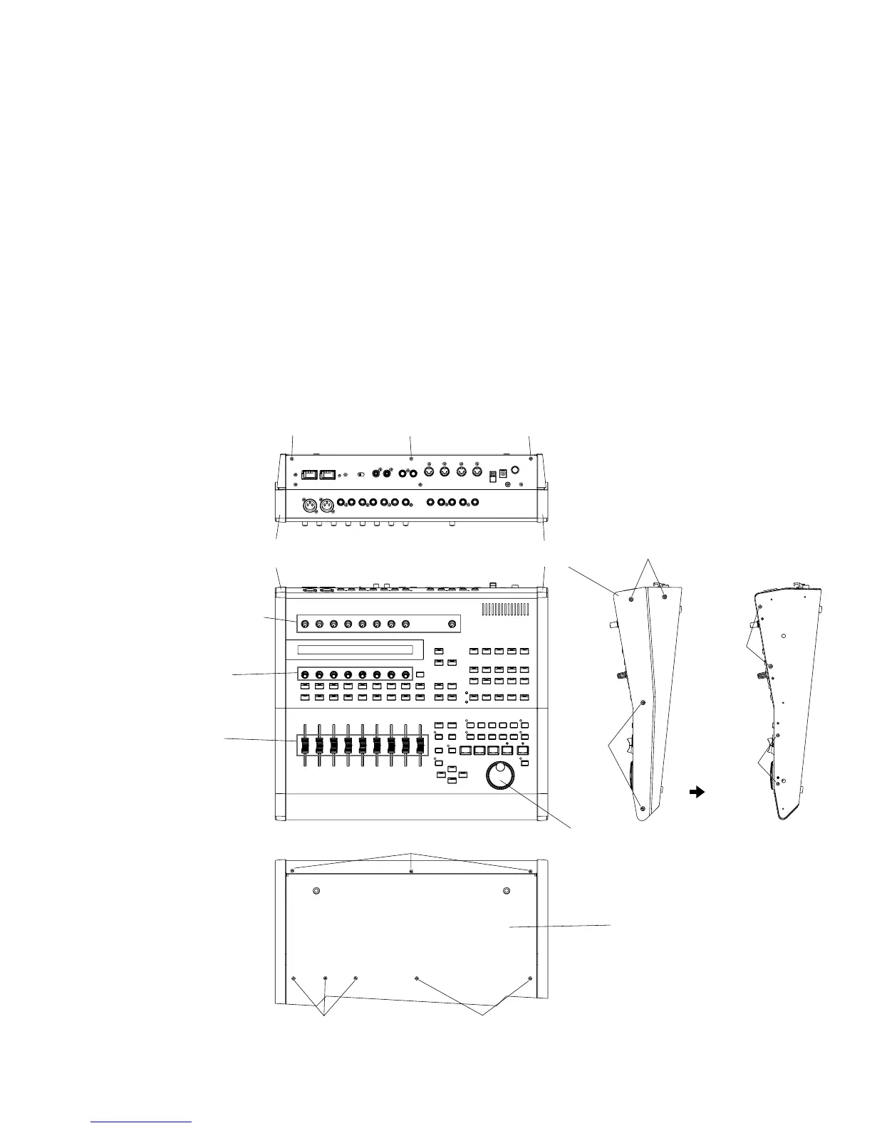
● Top view
● Rear view
2. Bottom Cover
(Time required : About 2 min.)
2-1. Remove the side panels L and R. (See procedure 1)
2-2. Remove the four (4) screws marked [112A] from the
side panel R and from the side panel L as well. (Fig. 1)
2-3. Remove the three (3) screws marked [112B] from the
rear panel. (Fig. 1)
1. Side Panel (L, R)
(Time required : About 1 min.)
Remove the four (4) screws marked [140]. The side panel
R can then be removed. (Fig. 1)
* The side panel L can then be removed in the same
manner.
■ DISASSEMBLY PROCEDURE
(分解手順)
(Fig. 1)
[140]: Bind Head Tapping Screw-B 3.0 x 20 MFZN2BL (VJ999700)
[112]: Bind Head Tapping Screw-S 3.0 x 6 MFZN2BL (EP630210)
2. ボトムカバー (所要時間:約2分)
2-1. サイドパネルL、Rを外します。(1項参照)
2-2. 右面の[112A]のネジ4本を外し、同様に左面のネジ4本
も外します。(Fig.1)
2-3. リア面の[112B]のネジ3本を外します。(Fig.1)
1. サイドパネル(L・R) (所要時間:約1分)
[140]のネジ4本を外し、サイドパネルRを外します。
(Fig.1)
※ サイドパネルLも同様にして外します。
+バインドBタイト
+バインドSタイト
● Bottom view
Side panel L
(サイドパネルL)
Knobs and VR knob bushings
(ノブ(上)極小、VRブッシュ)
Encoder knobs
(エンコーダノブ)
Bottom cover
(ボトムカバー)
Side panel R
(サイドパネルR)
[112B] [112B] [112B]
[140]
[140]
[112A]
[112C]
[112C][112C]
[112A]
Slider knobs
(スライダーノブ)
Dial knob
(ダイアルツマミ)
13
2