14
O1X
3. DM Circuit Board, MLN2 Circuit Board
(Time required : About 3 min.)
3-1. Remove the side panel L and R. (See procedure 1)
3-2. Remove the Bottom cover. (See procedure 2)
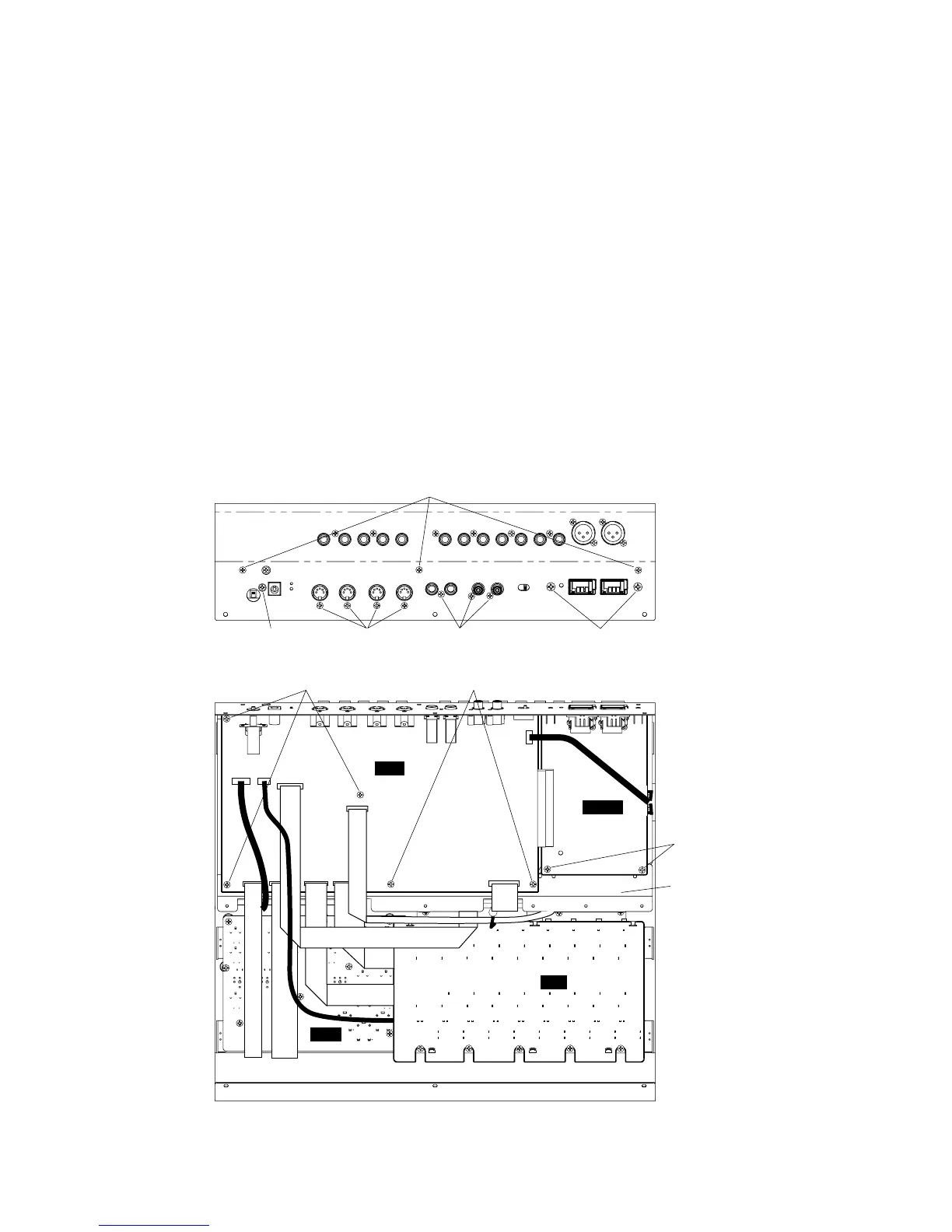
3-3. Remove the seven (7) screws marked [95]. (Fig. 2)
3-4. Remove the eight (8) screws marked [96] and the two
(2) screws marked [97]. The DM cicuit board and the
MLN2 cicuit board can then be removed. (Fig. 2)
* When installing the DM circuit board and MLN2 circuit
board, tighten the screws "1 and 2" of those marked [96]
of the rear panel first.
3-5. Remove the MLN2 cicuit board from the DM cicuit
board.
[95]: Bind Head Tapping Screw-S 3.0 x 6 MFZN2BL (EP630210)
[96]: Bonding Head Tapping Screw-B 3.0 x 10 MFZN2BL (VQ049800)
[97]: Bind Head Screw 4.0 x 6 MFZN2BL (EG340340)
[102]: Bind Head Tapping Screw-S 3.0 x 6 MFZN2BL (EP630210)
● Rear view
● Bottom view
MF
DM
MLN2
1
2
DM shield plate
(DMシールド
[95]
[97]
[102]
[96][96][96]
[95] [95]
PN1
2-4. Remove the eight (8) screws marked [112C] from the
bottom cover. The bottom cover can then be removed.
(Fig. 1)
* When installing the bottom cover, tighten the "1, 2 and
3" screws of those marked [112B] of the rear panel first.
2-4. ボトム面の[112C]のネジ8本を外し、ボトムカバーを外
します。(Fig.1)
※ ボトムカバーの取り付けの際は、リア面の[112B]ネジ1→3
を先に締めます。
(Fig. 2)
3. DM、MLN2シート (所要時間:約3分)
3-1. サイドパネルL、Rを外します。(1項参照)
3-2. ボトムカバーを外します。(2項参照)
3-3. [95]のネジ7本を外します。(Fig.2)
3-4. リア面の[96]のネジ8本、[97]のネジ2本を外し、DM
シートとMLN2シートを外します。(Fig.2)
※ DMシート、MLN2シートの取り付けの際は、リア面の[96]ネ
ジ1→2を先に締めます。
3-5. DMシートからMLN2シートを外します。
+バインドSタイト
ボンディングBタイト
+バインド小ネジ
+バインドSタイト