68
O1X
3. Test Entry
3.1 Test entry
To enter the TEST mode, operate the buttons on the panel of the
main unit according to the following procedure.
1
Turn on the power while pressing the [UTILITY] and
[AUDIO] buttons, and the messages appear on the display
in the order as shown below.
<Start-up screen>
YAMAHA O1X DIGITAL MIXING STUDIO
(C)2003 YAMAHA CORPORATION
Keep pressing the [UTILITY] and [AUDIO] keys until this
message appears.
O1X (C) 2003 YAMAHA CORPORATION BOOT OS:V#.###
BUILT DATE: 2003/**/** FIRM OS:V#.###
When the [UTILITY] and [AUDIO] buttons are released,
the following message appears on the display.
##### O1X DIAGNOSTICS PROGRAM ##### ______________-----
01:CPU MEMORY RECALL
<Execution item select screen>
##### O1X DIAGNOSTICS PROGRAM ##### ______________-----
02:SWITCH RECALL
2
When executing a test, select the test item by turning
[KNOB-1] and execute testing by pressing [KNOB-8].
3
When the test item is completed as OK and when it is
terminated before the end, pressing the [KNOB-7] or
[KNOB-8] brings back the menu screen. On this screen, the
test result is displayed in the test item space, that is, "O":
completed as OK, "X": terminated before the end, " ": not
checked yet, "-": testing not applicable. Also, when
completed as OK, the next check item is displayed on the
LCD. The selected item flashes.
4
When [RECALL] is pressed, the check item name is
displayed in the screen of the check items to be executed in
the upper section.
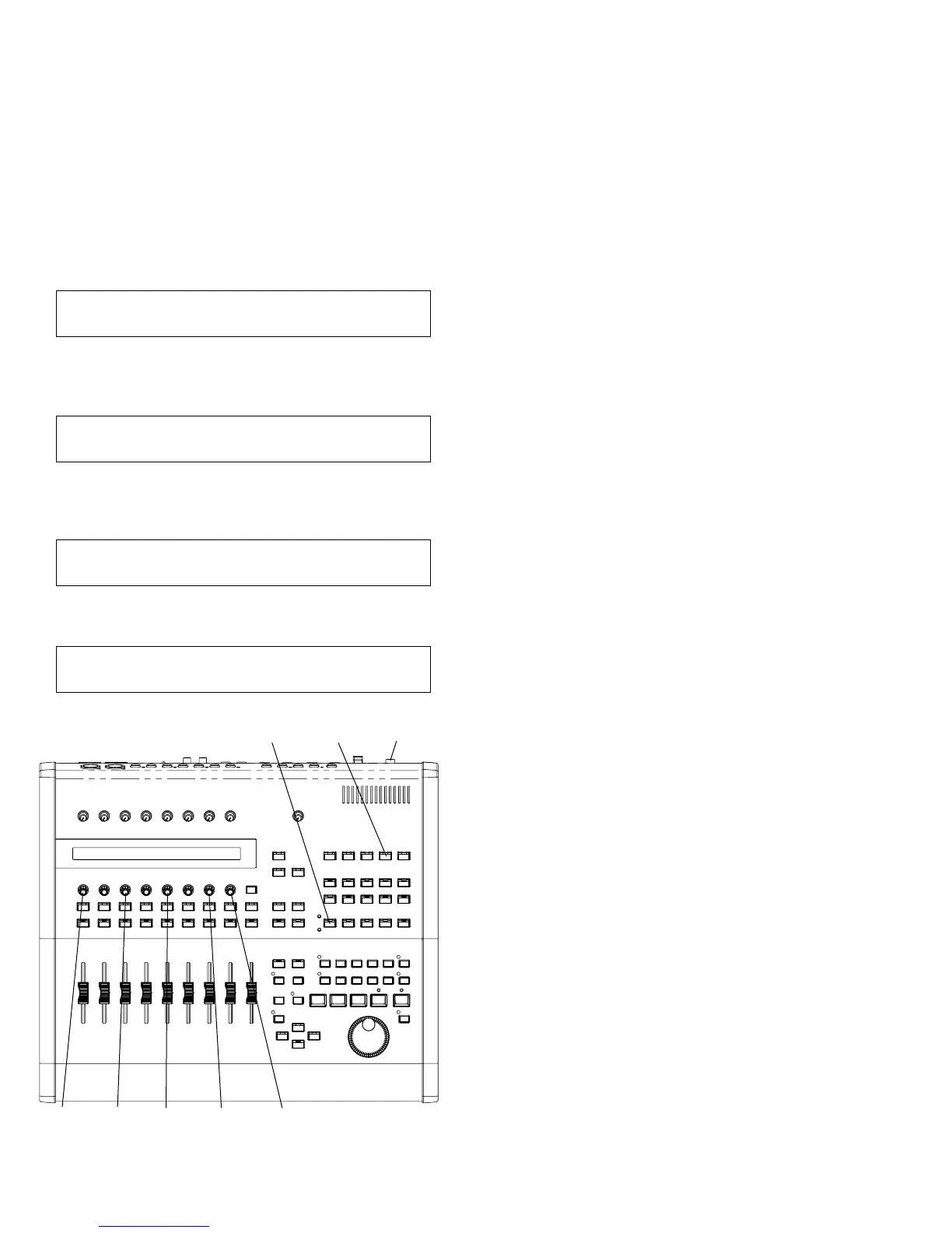
UTILITYAUDIO STANDBY/ON
KNOB-1 KNOB-8KNOB-3 KNOB-7KNOB-5
3.2 Other functions
The moving fader can be shifted to the positions as listed below
by pressing the corresponding keys. This function is usable for
the operation check of the fader.
[AUDIO]: +6dB ([AUDIO] is SW201 on the PN2
circuit board.)
[INST]: 0dB ([INST] is SW202 of the PN2 circuit
board.)
[MIDI]: -20dB ([MIDI] is SW203 of the PN2 circuit
board.)
[BUS/AUX]: -∞ ([BUS/AUX] is SW204 of the PN2
circuit board.)
The condition of the word clock and I/O connection of DSP at
the time of starting are as follows.
Even when a check item requiring a change of these conditions
is executed, these conditions are restored when that check is
over.
Word clock: 48KHz Internal
DSP I/O: AD5-8->DA1-4, AD1-2->Digital Out
3.3 Confirmation of version
To check the version of the BOOT OS and FIRM OS, turn on
the power while pressing the [UTILITY] button. The version is
displayed on the LCD.