2-1
GB
q
e
r
t
y
u
i
o
!1
!3
!4
101092
!2
TRIPTRIP TIMETIME BATTBATT
Km/hKm/h
knot
mphmph
km
mile
SPEEDSPEED
YAMAHA
setset
modemode
!6
!7
!8
!9
@0
!0
w
1
2
3
4
5
x100
r/min
TACH
802043
!5
!1
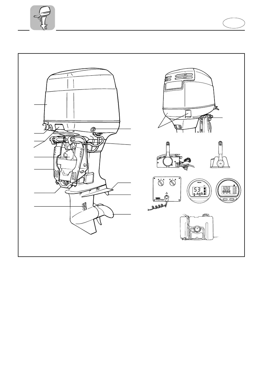
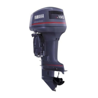
EMU01206
MAIN COMPONENTS
1 Power trim and tilt switch
2 Tilt support lever
3 Anti-cavitation plate
4 Trim tab (Anode)
5 Propeller
6 Cooling water inlet
7 Anode
8 Clamp bracket
9 Power trim and tilt unit
0 Cowling release lever
q Cowling lock lever
w Choke knob
e Top cowling
r Cooling water pilot hole
t Remote control box (Side mount type)
y Remote control box (Binnacle mount type)
u Switch panel (Together with y)
i Digital tachometer
o Digital speedometer
p Remote oil tank
*1. V4 engine type
*2. V6 engine type
*3. Counter rotation model
*1
*3
*3
*2
* May not be exactly as shown; also may not be
included as standard equipment on all models.
*
*
*
*
*
64C-9-76 (E,F,ES) 2 4/25/0 2:53 PM Page 24