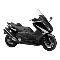
Do you have a question about the Yamaha 2012 TMAX XP500A and is the answer not in the manual?
| Engine Type | Liquid-cooled, 4-stroke, DOHC, 4-valve |
|---|---|
| Displacement | 499cc |
| Bore x Stroke | 66.0 mm x 73.0 mm |
| Compression Ratio | 11.0 : 1 |
| Fuel System | Fuel Injection |
| Transmission | V-Belt Automatic |
| Final Drive | Belt |
| Front Suspension | Telescopic forks |
| Rear Suspension | Swingarm |
| Front Brake | Dual hydraulic disc |
| Front Tire | 120/70-15 |
| Rear Tire | 160/60-15 |
| Width | 775 mm |
| Seat Height | 800 mm |
| Wheelbase | 1, 580 mm |
| Ground Clearance | 125 mm |
| Wet Weight | 217 kg |
| Ignition | TCI |
| Curb Weight | 217 kg |
| Rear Brake | Single hydraulic disc |
| Fuel Capacity | 15 liters |
| Length | 2, 200 mm |
| Height | 1420mm |
| Maximum Torque | 52.3 Nm (5.3 kg-m) @ 6, 250 rpm |
Torque values for standard fasteners and engine/chassis components.
Comprehensive schedule for checks, maintenance, and lubrication at different intervals.
Procedures for checking fuel lines, spark plugs, valve clearance, and idling speed.
Checking brake fluid, pads, hoses, and bleeding the hydraulic system.
Procedures for checking engine oil level, changing oil, and checking coolant.
Steps for removing, disassembling, checking, and installing the front wheel.
Steps for removing, disassembling, checking, and installing the rear wheel.
Procedures for removing/disassembling brake pads, calipers, master cylinder.
Procedures for removing/disassembling brake pads, caliper, master cylinder, and lock.
Procedures for removing the hydraulic unit assembly and related components.
Steps for removing, disassembling, checking, assembling, and installing front fork legs.
Procedures for removing, checking, and installing steering head components.
Initial checks including compression pressure measurement.
Steps for removing and installing the engine assembly and related components.
Procedures for removing, disassembling, checking, and installing V-belt and sheaves.
Procedures for removing crankshaft, connecting rods, bearings, and checking runout.
Circuit diagram and troubleshooting steps for the ignition system.
Circuit diagram and troubleshooting for the electric starting system.
Circuit diagram and troubleshooting steps for the charging system.
Circuit diagram and troubleshooting for headlights, taillights, and indicators.
Circuit diagram and detailed troubleshooting for the ABS system.
Guide for diagnosing ABS warning light behavior and related malfunctions.
Information on diagnostic codes, sensor operation checks, and actuator tests.