101141*
q
w
r
t
u
o
!5
!3
!2
!1
!0
i
!4
y
e
902056
2-2
GB
EMU01206
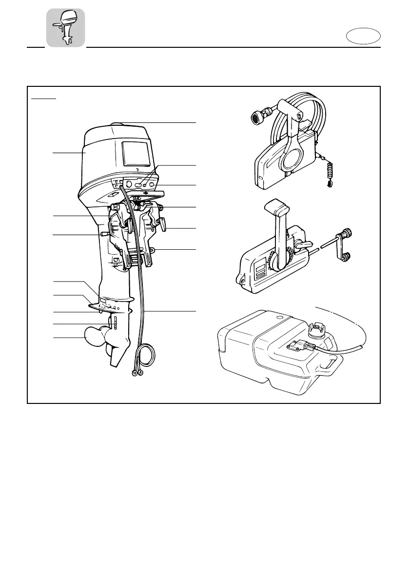
MAIN COMPONENTS
1 Oil filler access cap
2 Warning indicator lamps
3 Choke knob
4 Tilt lock lever
5 Transom clamp handle
6 Trim angle adjusting rod
7 Battery lead
8 Propeller
9 Cooling water inlet
0 Trim tab (Anode)
q Anti-cavitation plate
w Anode
e Tilt support lever
r Clamp bracket
t Top cowling
y Remote control box
u Fuel tank
*1 Manual start model
*2 Electric start model
*3 It differs on specifications
* May not be exactly as shown; also may not
be included as standard equipment on all
models.
40VEO
!6
!7
*
3.
*
1.
*
2.
*
3.
63B-9-78-A0-2 2/17/03 4:26 PM Page 6