*5 For CH 2, GUITAR switch is ON
*6 Tip = Signal L, Ring = Signal R, Sleeve = GND
*7 Tip = Signal L, Ring 1 = Signal R, Ring 2 = GND, Sleeve = Output for smartphone
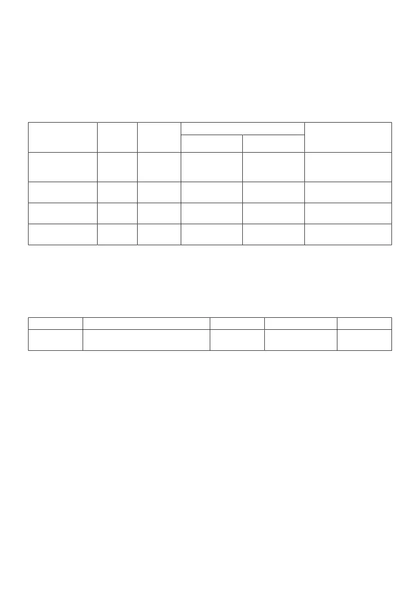
Analog Output Characteristics
0 dBu = 0.775 Vrms
Output Terminals
Actual
Source
Impedance
Nominal
impedance
Output level
Connectors
Nominal Max. before clip
MONITOR OUT [L, R] 150 Ω 10 kΩ line
+4 dBu
(1.228 V)
+14 dBu
(3.884 V)
XLR-3-32 *8
Phone jack *9
(balanced)
MIX OUT [L, R] 150 Ω 10 kΩ line
+4 dBu
(1.228 V)
+14 dBu
(3.884 V)
Phone jack *9
(balanced)
PHONES 120 Ω 40 Ω phone 1.5 mW + 1.5 mW 6 mW + 6 mW
Phone jack
3.5 mm phone jack
AUX OUT 150 Ω 1.5 kΩ line
−30 dBu
(24.51 mV)
−20 dBu
(77.50 mV)
3.5 mm phone jack *10
(CTIA)
*8 1 = Ground, 2 = Hot, 3 = Cold
*9 Tip = HOT, Ring = COLD, Sleeve = GND
*10 Tip = Signal L, Ring 1 = Signal R, Ring 2 = GND, Sleeve = Output for smartphone
Digital Input / Output Characteristics
Terminals Format Data Length Fs Connectors
USB
USB Audio Class 2.0 / Yamaha Steinberg
USB Driver
24-bit 48 kHz USB Type-C
The contents of this guide apply to the latest specifications as of the publishing date.
79
Appendix > Input / Output characteristics