EasyManua.ls Logo

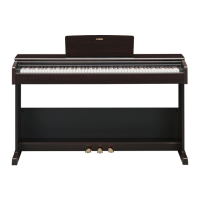
Yamaha Arius YDP-161 User Manual

Yamaha Arius YDP-161
96 pages
To Next Page IconTo Next Page
Page #1 background imageLoading...
Page #1 background image
SERVICE MANUAL
HAMAMATSU, JAPAN
SERVICE MANUAL
YDP-161/YDP-161C: 20100401-
オーンプライス
CL
001842
Copyright (c) Yamaha Corporation. All rights reserved. PDF ’10.03
DIGITAL PIANO
YDP-161/YDP-161C
SPECIFICATIONS(総合仕様) ...............................3/4
PANEL LAYOUT(パネルレイアウト) ....................... 5
DISASSEMBLY PROCEDURE(分解手順) ...............6
LSI PIN DESCRIPTION(LSI 端子機能表) .............. 21
CIRCUIT BOARDS(シート基板図) ........................26
TEST PROGRAM(テストプログラム) ..............36/40
INITIAL SETTING(出荷時の設定) .......................... 44
BACKING UP DATA AND INITIALIZING THE SETTINGS
(バックアップデータと初期化)
...............................45/46
DATA BACKUP(データのバックアップ) ..........47/51
SYSTEMBOOTINGFLOWCHART
(起動フローチャート) .........................................55/56
PARTS LIST
BLOCK DIAGRAM(ブロックダイアグラム)
CIRCUIT BOARD LAYOUT & WIRING
ユニットレイアウト & 結線図)
OVERALL CIRCUIT DIAGRAM(総回路図)
CONTENTS(目次)
●YDP-161 ●YDP-161C

Other manuals for Yamaha Arius YDP-161

Question and Answer IconNeed help?

Do you have a question about the Yamaha Arius YDP-161 and is the answer not in the manual?

Yamaha Arius YDP-161 Specifications

General IconGeneral
TypeDigital Piano
Number of Keys88
Key ActionGraded Hammer Standard (GHS)
Touch SensitivityHard/Medium/Soft/Fixed
Voices14
EffectsReverb, Chorus
ReverbYes
ChorusYes
MetronomeYes
RecorderYes
Recording1 song, 2 tracks
Amplifiers20W x 2
Speakers12 cm x 2
Polyphony128
Sound SourceAWM (Advanced Wave Memory) Stereo Sampling
Pedals3 (Damper, Sostenuto, Soft)
ConnectionsMIDI In/Out
Included AccessoriesOwner's Manual
Sound EngineAWM (Advanced Wave Memory) Stereo Sampling

Summary

Digital Piano Arius YDP-161/YDP-161C Service Manual

Important Service and Safety Notices

Product Specifications

Panel Layout Overview

Control Panel Components Identification

Identification of buttons, knobs, and switches on the control panel.

Jacks, Terminals, and Pedals Identification

Identification of audio, MIDI, power, and pedal jacks/terminals.

Disassembly Procedures

Exterior Section Disassembly Steps

Steps for removing exterior assemblies like headphone hanger, top board, main unit, etc.

Main Unit Circuit Boards and Assemblies

Main Unit Component Removal Procedures

Detailed list of screws and steps for removing circuit boards and assemblies.

PSM Circuit Board and Power Transformer Removal

Power Transformer Removal Steps

Steps for desoldering and removing the power transformer from the PSM circuit board.

DJACK Circuit Board Removal

Key Cover Assembly Removal

Rack (L, R) Removal

Stopper Rail Assembly Removal

Key Block Assembly (L, R) Removal

Keyboard Assembly (GHD EBUS) Removal

VR and PN Circuit Board Removal

VR Circuit Board Removal Steps

Steps for removing the VR circuit board using screws [9A].

PN Circuit Board Removal Steps

Steps for removing the PN circuit board using screws [9B].

PSW Connector Assembly (Power Switch) Removal

HP Circuit Board Removal

PL Circuit Board Removal

Back Top Rail Assembly Removal

Front Rail Assembly Removal

Side Arm Assembly (L, R) Removal

Stand Base Removal

Pedal Assembly Removal

PEDAL Circuit Board Removal

Keyboard Disassembly Procedures

GHD EBUS L and MK SUB Circuit Board Removal

Remove screws [260A] to detach GHD EBUS L and MK SUB boards.

GHD M Circuit Board Removal

Remove screws [260B] and [262] to detach the GHD M circuit board.

Keyboard Component Disassembly

GHD H Circuit Board Removal

Remove screws [260C] and [262] to detach the GHD H circuit board.

Rubber Contact Removal

Remove GHD circuit board and then remove rubber contacts.

White Key Removal Procedure

Steps to release white key from stopper, move rearward, and remove.

Hammer and White Key Removal

Keyboard Assembly Procedures

Hammer and White/Black Key Assembly

Assemble hammer assembly into frame, add stopper (L88_W). Four types of hammers exist.

White and Black Key Assembly Steps

GHD EBUS L and MK SUB Circuit Board Installation

GHD M Circuit Board Installation

GHD H Circuit Board Installation

Circuit Board Diagrams

DM Circuit Board Diagram

MAL2 Circuit Board Diagram

PEDAL Circuit Board Diagram

HP Circuit Board Diagram

PL Circuit Board Diagram

MK SUB Circuit Board Diagram

GHD EBUS L Circuit Board Diagram

GHD M Circuit Board Diagram

GHD H Circuit Board Diagram

PSM Circuit Board Diagram

Test Program Overview

Test Program Preparations

Required items and initial settings for conducting tests.

Entering the Test Program

Procedure to start the test program by pressing specific keys and power.

Proceeding Through Test Items

How to select and execute test items using keys and the DEMO/SONG button.

Test Items List and Conditions

ROM Version Check (Main & Wave ROM)

Verifies Main and Wave ROM versions by checking specific key presses and sounds.

ROM Check 1 (CPU Bus)

Checks ROM checksum connected to the CPU bus for correct operation.

RAM Check 1 (CPU Bus)

Checks RAM connection condition connected to the CPU bus.

Flash ROM Check 1 (Specific Bank)

Tests erase, write, read functions for specific Flash ROM banks.

Wave ROM Check 1 (Tone Generator LSI)

Checks ROM checksum connected to the tone generator LSI bus.

Effect RAM Check 1 (Tone Generator LSI)

Checks Effect RAM connection to the tone generator LSI bus.

TG1 Check (Auto Scaling)

Pitch Check

Output Level Check (Right Channel)

Output Level Check (Left Channel)

Switch Check

Pedal 1 Check (Soft Pedal)

Pedal 2 Check (Sostenuto Pedal)

Pedal 3 Check (Damper Pedal)

MIDI Check Procedure

Keyboard Type Check

ROM Check 2 (Full Address)

RAM Check 2 (Full Address)

Flash ROM Check 2 (Erasure, Write, Read)

Wave ROM Check 2 (Checksum)

Effect RAM Check 2 (Checksum)

Factory Set Initialization Procedure

Data Backup and Initialization Procedures

Backing Up Data to Flash Memory

Lists items stored in flash memory (Metronome, Tuning, User Song, etc.).

Initializing Settings Procedure

Procedure to initialize settings by holding C7 and turning power on.

Data Backup Procedures

Data Backup Contents

Lists user song, backup data (10YDP.BUP), and loaded song data.

Data Backup Preparation Steps

PC, UX16, USB-MIDI Driver, and Musicsoft Downloader setup.

Backup Procedure Steps

Step-by-step guide for backing up data using Musicsoft Downloader.

Troubleshooting MIDI IN/OUT Settings

System Booting Flowchart

System Booting Flowchart Steps

Detailed breakdown of the system booting process and decision points.

Parts List Overview

Component Replacement Warning

Warning about replacing critical components with specified parts only.

Keyboard Assembly (GHD EBUS) Diagrams

Electrical Parts List (DJACK and DM)

Electrical Parts (DM, GHD EBUS L, MK SUB, GHD H, GHD M)

Electrical Parts (GHD M, HP, MAL2)

Electrical Parts (MAL2, PEDAL, PL, PN/VR)

Electrical Parts (PN/VR, PSM)

Overall Circuit Diagram 1/3 (Block Diagram)

Block Diagram Overview

High-level block diagram showing system interconnections.

Circuit Board Layout and Wiring Diagram

Diagram showing physical layout and wiring of main circuit boards.

Overall Circuit Diagram 2/3 (DM, HP, MAL2, PL, PN, VR)

DM Circuit Diagram (2/3)

Detailed circuit diagram for the DM component (part 2/3).

DM Circuit Diagram (3/3)

Detailed circuit diagram for the DM component (part 3/3).

HP Circuit Diagram

Circuit diagram for the HP component.

MAL2 Circuit Diagram

Circuit diagram for the MAL2 component.

PN Circuit Diagram

Circuit diagram for the PN component.

VR Circuit Diagram

Circuit diagram for the VR component.

Overall Circuit Diagram 3/3 (DJACK, GHD EBUS L, GHD H, GHD M, MK SUB, PEDAL, PSM)

GHD EBUS L Circuit Diagram

Detailed circuit diagram for the GHD EBUS L component.

MK SUB Circuit Diagram

Circuit diagram for the MK SUB component.

GHD M Circuit Diagram

Detailed circuit diagram for the GHD M component.

GHD H Circuit Diagram

Detailed circuit diagram for the GHD H component.

DJACK Circuit Diagram

Circuit diagram for the DJACK component.

PEDAL Circuit Board Diagram

Circuit diagram for the PEDAL component.

PSM Circuit Diagram

Circuit diagram for the PSM component.

Related product manuals