Do you have a question about the Yamaha AX-390 and is the answer not in the manual?
Critical warnings and disclaimers for authorized service personnel.
Critical warnings on safety procedures, static discharge, and proper handling.
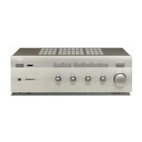
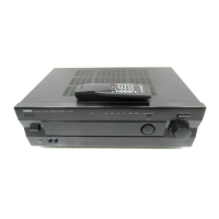
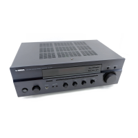
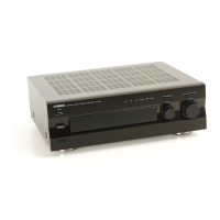
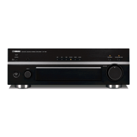
Details the rear panel connections and configurations for different model variants.
Detailed performance metrics for the audio circuitry.
Power supply, consumption, dimensions, and weight details.
Step-by-step guide for dismantling the amplifier unit.
Detailed pin assignments and functions for the µ-COM IC.
Pin connection diagrams for various integrated circuits used.
Pinouts for diodes and transistors.
Locations of semiconductors on the Operation PCB.
Block diagrams for TC4052BP and TC4053BP multiplexer ICs.
Block diagrams for NJM2068L-D Op-Amp and LB1641 Motor Driver ICs.
List of abbreviations used for electrical components in the parts list.
Comprehensive list of electrical components with part numbers and descriptions.
List of mechanical components including front panel parts, chassis, and buttons.
| Power Output | 40W per channel (8 ohms, 20Hz-20kHz, 0.04% THD) |
|---|---|
| Frequency Response | 10Hz-100kHz (+0/-3dB) |
| Signal-to-Noise Ratio | 100dB (CD input) |
| Input Sensitivity | 2.5mV (MM), 150mV (line) |
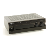
| Dimensions | 435 x 151 x 388mm (W x H x D) |
| Weight | 8.5 kg |
| Total harmonic distortion | 0.04% (20Hz-20kHz, 40W, 8 ohms) |
| Damping factor | 100 |
| Total Harmonic Distortion (THD) | 0.04% |
| Signal to noise ratio | 100 dB |