EasyManua.ls Logo

Yamaha AX-396 Service Manual

Yamaha AX-396
42 pages
To Next Page IconTo Next Page
Page #1 background imageLoading...
Page #1 background image
AX-496/396
SERVICE MANUAL
STEREO AMPLIFIER
AX-496/396
100702
CONTENTS
SPECIFICATIONS.......................................................... 1
TO SERVICE PERSONNEL .......................................... 2
REMOTE CONTROL PANEL ........................................ 2
IMPEDANCE SELECTOR ............................................. 2
FRONT PANELS ............................................................ 3
REAR PANELS .............................................................. 3
INTERNAL VIEW ........................................................... 6
DISASSEMBLY PROCEDURES ................................... 6
ADJUSTMENTS ............................................................. 7
BLOCK DIAGRAM ......................................................... 8
µ-COM DATA ................................................................. 9
PRINTED CIRCUIT BOARD .................................. 10~25
SCHEMATIC DIAGRAM ........................................ 26~29
PARTS LIST ........................................................... 30~47
REMOTE CONTROL TRANSMITTER ........................ 48
IMPORTANT NOTICE
This manual has been provided for the use of authorized YAMAHA Retailers and their service personnel.
It has been assumed that basic service procedures inherent to the industry, and more specifically YAMAHA Products,
are already known and understood by the users, and have therefore not been restated.
WARNING: Failure to follow appropriate service and safety procedures when servicing this product may result
in personal injury, destruction of expensive components, and failure of the product to perform as
specified. For these reasons, we advise all YAMAHA product owners that any service required
should be performed by an authorized YAMAHA Retailer or the appointed service representative.
IMPORTANT: The presentation or sale of this manual to any individual or firm does not constitute authorization,
certification or recognition of any applicable technical capabilities, or establish a principle-agent
relationship of any form.
The data provided is believed to be accurate and applicable to the unit(s) indicated on the cover. The research,
engineering, and service departments of YAMAHA are continually striving to improve YAMAHA products.
Modifications are, therefore, inevitable and specifications are subject to change without notice or obligation to
retrofit. Should any discrepancy appear to exist, please contact the distributor's Service Division.
WARNING: Static discharges can destroy expensive components. Discharge any static electricity your body
may have accumulated by grounding yourself to the ground buss in the unit (heavy gauge black
wires connect to this buss).
IMPORTANT: Turn the unit OFF during disassembly and part replacement. Recheck all work before you apply
power to the unit.
AX-496/396
P.O.Box 1, Hamamatsu, Japan
Question and Answer IconNeed help?

Do you have a question about the Yamaha AX-396 and is the answer not in the manual?

Yamaha AX-396 Specifications

General IconGeneral
Channel Separation55 dB (1 kHz)
Frequency Response20Hz to 20kHz
Signal-to-Noise Ratio100 dB (CD)
Input Sensitivity/Impedance150mV/47k ohms (CD)
Dimensions (W x H x D)435 x 151 x 387 mm
Input Sensitivity150 mV
Signal to Noise Ratio100 dB (CD)
Speaker Load Impedance4 ohms (min)

Summary

Specifications

Power Section Specifications

Details of output power, band width, damping factor, and frequency response.

General Specifications

Includes power supply, consumption, dimensions, weight, accessories, and color options.

Dimensional Specifications

Physical dimensions of the unit including W x H x D.

To Service Personnel

Critical Components Information

Guidance on replacing components with special characteristics.

Leakage Current Measurement Procedure

Procedure and limits for verifying insulation from supply circuits.

Chemical Content Notice

Warning about lead and other chemicals used in the product.

Remote Control Panel

Remote Control Layout

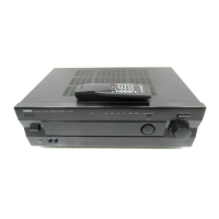
Diagram showing the layout of the remote control buttons.

Impedance Selector

Impedance Selector Operation Warning

Instruction and warning for changing impedance selector settings.

Front Panels

AX-496 Front Panel Controls

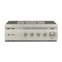
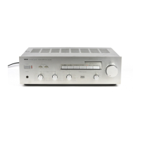
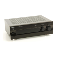
Description of the front panel controls and indicators for AX-496.

AX-396 Front Panel Controls

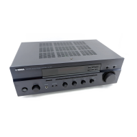
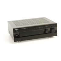
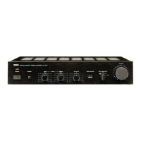
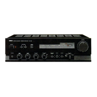
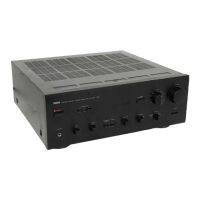
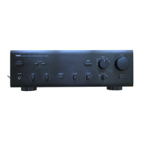
Description of the front panel controls and indicators for AX-396.

Rear Panels (AX-496)

AX-496 R Model Rear Panel

Layout of rear connections for AX-496 R model.

AX-496 T Model Rear Panel

Layout of rear connections for AX-496 T model.

AX-496 B Model Rear Panel

Layout of rear connections for AX-496 B model.

AX-496 G Model Rear Panel

Layout of rear connections for AX-496 G model.

AX-496 A, B, G, J Models Rear Panels

Layout of rear connections for AX-496 A, B, G, J models.

Rear Panels (AX-396)

AX-396 R Model Rear Panel

Layout of rear connections for AX-396 R model.

AX-396 A, B, G, J Models Rear Panels

Layout of rear connections for AX-396 A, B, G, J models.

Internal View

Internal Component Layout

Diagram identifying internal PCB components.

Disassembly Procedures

Removal of Top Cover

Steps to remove the top cover of the unit.

Removal of Front Panel

Steps to remove the front panel of the unit.

MAIN P.C.B. (1) Removal

Steps to check and replace the main PCB.

Adjustments

Confirmation of Idling Current

Procedure to confirm and adjust idling current.

Block Diagram

AX-496 Block Diagram

Functional block diagram for AX-496.

AX-396 Block Diagram

Functional block diagram for AX-396.

μ-COM Data

IC101: M37478M4-409SP Pinout

Pin configuration and function for the μ-COM IC.

Printed Circuit Board (AX-496)

P.C.B. MAIN (3) Foil Side

Foil side layout of the main PCB (3).

P.C.B. MAIN (1) Foil Side

Foil side layout of the main PCB (1).

Printed Circuit Board (AX-496)

P.C.B. MAIN (2) Foil Side

Foil side layout of the main PCB (2).

P.C.B. MAIN (4) (R, T models) Foil Side

Foil side layout of main PCB (4) for R, T models.

P.C.B. MAIN (5) (R, T models) Foil Side

Foil side layout of main PCB (5) for R, T models.

P.C.B. MAIN (6) Foil Side

Foil side layout of main PCB (6).

P.C.B. MAIN (8) (B, G models) Foil Side

Foil side layout of main PCB (8) for B, G models.

P.C.B. MAIN (9) Foil Side

Foil side layout of main PCB (9).

Printed Circuit Board (AX-496)

P.C.B. FUNCTION (6) Foil Side

Foil side layout of Function PCB (6).

P.C.B. FUNCTION (3) Foil Side

Foil side layout of Function PCB (3).

P.C.B. FUNCTION (1) Foil Side

Foil side layout of Function PCB (1).

P.C.B. FUNCTION (2) Foil Side

Foil side layout of Function PCB (2).

Printed Circuit Board (AX-496)

P.C.B. FUNCTION (4) Foil Side

Foil side layout of Function PCB (4).

P.C.B. FUNCTION (5) Foil Side

Foil side layout of Function PCB (5).

P.C.B. FUNCTION (7) Foil Side

Foil side layout of Function PCB (7).

P.C.B. FUNCTION (9) Foil Side

Foil side layout of Function PCB (9).

P.C.B. FUNCTION (8) Foil Side

Foil side layout of Function PCB (8).

P.C.B. FUNCTION (10) Foil Side

Foil side layout of Function PCB (10).

P.C.B. FUNCTION (11) Foil Side

Foil side layout of Function PCB (11).

Printed Circuit Board (AX-396)

P.C.B. MAIN (3) Foil Side

Foil side layout of the main PCB (3) for AX-396.

P.C.B. MAIN (1) Foil Side

Foil side layout of the main PCB (1) for AX-396.

Printed Circuit Board (AX-396)

P.C.B. MAIN (2) Foil Side

Foil side layout of the main PCB (2) for AX-396.

P.C.B. MAIN (5) (R model) Foil Side

Foil side layout of main PCB (5) for AX-396 R model.

P.C.B. MAIN (4) (R model) Foil Side

Foil side layout of main PCB (4) for AX-396 R model.

P.C.B. MAIN (7) Foil Side

Foil side layout of main PCB (7) for AX-396.

P.C.B. MAIN (8) (A, B, G models) Foil Side

Foil side layout of main PCB (8) for AX-396 A, B, G models.

P.C.B. MAIN (9) Foil Side

Foil side layout of main PCB (9) for AX-396.

Printed Circuit Board (AX-396)

P.C.B. FUNCTION (6) Foil Side

Foil side layout of Function PCB (6) for AX-396.

P.C.B. FUNCTION (3) Foil Side

Foil side layout of Function PCB (3) for AX-396.

P.C.B. FUNCTION (2) Foil Side

Foil side layout of Function PCB (2) for AX-396.

P.C.B. FUNCTION (1) Foil Side

Foil side layout of Function PCB (1) for AX-396.

Printed Circuit Board (AX-396)

P.C.B. FUNCTION (4) Foil Side

Foil side layout of Function PCB (4) for AX-396.

P.C.B. FUNCTION (5) Foil Side

Foil side layout of Function PCB (5) for AX-396.

P.C.B. FUNCTION (7) Foil Side

Foil side layout of Function PCB (7) for AX-396.

P.C.B. FUNCTION (9) Foil Side

Foil side layout of Function PCB (9) for AX-396.

P.C.B. FUNCTION (10) Foil Side

Foil side layout of Function PCB (10) for AX-396.

P.C.B. FUNCTION (8) Foil Side

Foil side layout of Function PCB (8) for AX-396.

P.C.B. FUNCTION (11) Foil Side

Foil side layout of Function PCB (11) for AX-396.

P.C.B. FUNCTION (12) Foil Side

Foil side layout of Function PCB (12) for AX-396.

Schematic Diagram (AX-496)

CD/DVD Direct Amp Section Schematic

Schematic of the CD/DVD Direct Amplifier section.

Input Selector Section Schematic

Schematic of the input selector circuitry.

Volume Amp Section Schematic

Schematic of the volume amplifier circuit.

Tone Control Amp Section Schematic

Schematic of the tone control amplifier circuit.

Protection Circuitry Schematic

Schematic of the protection circuit.

System Control Section Schematic

Schematic of the system control logic.

Pin Connection Diagrams

Pinouts for transistors, diodes, and ICs.

Schematic Diagram (AX-496)

Power Amp Section Schematic

Schematic of the power amplifier circuit.

Relay Driver Section Schematic

Schematic of the relay driver circuit.

Power Supply Section Schematic

Schematic of the power supply unit.

Impedance Selector Section Schematic

Schematic of the impedance selector circuit.

Schematic Diagram (AX-396)

CD/DVD Direct Amp Section Schematic

Schematic of the CD/DVD Direct Amplifier section for AX-396.

Input Selector Section Schematic

Schematic of the input selector circuitry for AX-396.

Volume Amp Section Schematic

Schematic of the volume amplifier circuit for AX-396.

Tone Control Amp Section Schematic

Schematic of the tone control amplifier circuit for AX-396.

Protection Circuitry Schematic

Schematic of the protection circuit for AX-396.

System Control Section Schematic

Schematic of the system control logic for AX-396.

Pin Connection Diagrams

Pinouts for transistors, diodes, and ICs.

Schematic Diagram (AX-396)

Power Amp Section Schematic

Schematic of the power amplifier circuit for AX-396.

Relay Driver Section Schematic

Schematic of the relay driver circuit for AX-396.

Power Supply Section Schematic

Schematic of the power supply unit for AX-396.

Impedance Selector Section Schematic

Schematic of the impedance selector circuit for AX-396.

Parts List

Electrical Parts List

List of electrical components with part numbers and descriptions.

Parts List Abbreviations

List of abbreviations used in the parts list.

Parts List (AX-496)

Capacitors List (AX-496)

List of capacitors used in AX-496.

Diodes and Transistors List (AX-496)

List of diodes and transistors used in AX-496.

Connectors and Fuses List (AX-496)

List of connectors and fuses used in AX-496.

Parts List (AX-496)

Transistors List (AX-496)

List of transistors used in AX-496.

Connectors and Components List (AX-496)

List of connectors and other components for AX-496.

Parts List (AX-496)

Capacitors List (AX-496)

List of capacitors used in AX-496.

ICs and Other Components List (AX-496)

List of ICs and other components for AX-496.

Parts List (AX-496)

Switches and Potentiometers List (AX-496)

List of switches and potentiometers for AX-496.

Parts List (AX-396)

Capacitors List (AX-396)

List of capacitors used in AX-396.

Diodes and ICs List (AX-396)

List of diodes and ICs used in AX-396.

Connectors and Fuses List (AX-396)

List of connectors and fuses used in AX-396.

Parts List (AX-396)

Transistors List (AX-396)

List of transistors used in AX-396.

Connectors and Components List (AX-396)

List of connectors and other components for AX-396.

Parts List (AX-396)

Capacitors List (AX-396)

List of capacitors used in AX-396.

ICs and Other Components List (AX-396)

List of ICs and other components for AX-396.

Parts List (AX-396)

Transistors and Resistors List (AX-396)

List of transistors and resistors for AX-396.

Switches and Potentiometers List (AX-396)

List of switches and potentiometers for AX-396.

Exploded View (AX-496)

Exploded View - Main Chassis Assembly

Exploded view of the main chassis assembly.

Exploded View - Front Panel Assembly

Exploded view of the front panel assembly.

Exploded View - Power Transformer Assembly

Exploded view of the power transformer assembly.

Mechanical Parts (AX-496)

Front Panels and Lenses (AX-496)

List of front panels and lenses for AX-496.

Chassis and Sub Panels (AX-496)

List of chassis and sub panels for AX-496.

Hinges and Buttons (AX-496)

List of hinges and buttons for AX-496.

Mechanical Parts (AX-496)

Power Transformers and Cords (AX-496)

List of power transformers and cords for AX-496.

Knobs and Buttons (AX-496)

List of knobs and buttons for AX-496.

Plates and Supports (AX-496)

List of plates and supports for AX-496.

Mechanical Parts (AX-496)

Screws and Fasteners (AX-496)

List of screws and fasteners for AX-496.

Accessories (AX-496)

List of accessories such as remote control and battery.

Exploded View (AX-396)

Exploded View - Main Chassis Assembly (AX-396)

Exploded view of the main chassis assembly for AX-396.

Exploded View - Front Panel Assembly (AX-396)

Exploded view of the front panel assembly for AX-396.

Exploded View - Power Transformer Assembly (AX-396)

Exploded view of the power transformer assembly for AX-396.

Mechanical Parts (AX-396)

Front Panels and Lenses (AX-396)

List of front panels and lenses for AX-396.

Chassis and Sub Panels (AX-396)

List of chassis and sub panels for AX-396.

Hinges and Buttons (AX-396)

List of hinges and buttons for AX-396.

Mechanical Parts (AX-396)

Power Transformers and Cords (AX-396)

List of power transformers and cords for AX-396.

Knobs and Buttons (AX-396)

List of knobs and buttons for AX-396.

Plates and Supports (AX-396)

List of plates and supports for AX-396.

Mechanical Parts (AX-396)

Screws and Fasteners (AX-396)

List of screws and fasteners for AX-396.

Accessories (AX-396)

List of accessories such as remote control and battery for AX-396.

Parts List for Carbon Resistors

1/4W Type Resistors

List of 1/4W carbon resistors with part numbers.

1/6W Type Resistors

List of 1/6W carbon resistors with part numbers.

Remote Control Transmitter

Remote Control Schematic Diagram

Schematic diagram of the remote control transmitter.

Remote Control Functions

List of remote control functions and their data codes.

Related product manuals