Do you have a question about the Yamaha AX-900 and is the answer not in the manual?
Critical warnings regarding personal injury and component damage from incorrect service.
Policy on manual sale; does not grant authorization or imply technical capability.
Guidance on preventing static discharge damage to sensitive components during service.
Essential advice to power off the unit during disassembly and recheck all work.
Information and procedures specifically for authorized Yamaha service technicians.
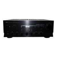
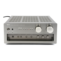
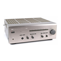
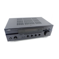
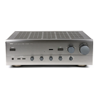
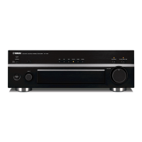
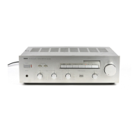
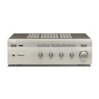
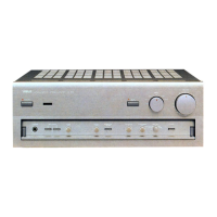
Detailed illustration and identification of the amplifier's front panel controls and displays.
Visual guide to rear panel input/output connectors and terminals for various model regions.
Comprehensive specifications detailing electrical performance, input/output capabilities, and physical dimensions.
Diagram showing the internal layout and identifying key components within the amplifier.
Diagram illustrating the overall signal path and functional blocks of the amplifier system.
Step-by-step instructions for safely dismantling the amplifier for maintenance or repair.
Detailed procedures for calibrating and adjusting critical parameters like idling current.
Pattern-side diagrams of the main and function circuit boards showing component placement.
Schematics illustrating the internal wiring and connections between different circuit boards.
Complete electronic circuit schematics for detailed troubleshooting and analysis.
A comprehensive list of all replaceable parts, including part numbers and descriptions.
| Signal to Noise Ratio | 120 dB |
|---|---|
| Dimensions | 435 x 170 x 450 mm |
| Input Sensitivity | 150mV (line) |
| Channel Separation | 70 dB |
| Speaker Load Impedance | 4Ω to 16Ω |
| Frequency Response | 5Hz-100kHz (+0/-3dB) |