Do you have a question about the Yamaha AX-892 and is the answer not in the manual?
Lists semiconductor component locations on the PCB.
Diagram of the Function Printed Circuit Board, section 2.
Diagram of the Function Printed Circuit Board, section 1.
Details on components requiring special attention during service.
Procedure for measuring leakage current after service.
Warning regarding hazardous chemical content in the product.
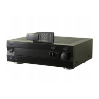
Overview of the remote control transmitter's panel layout.
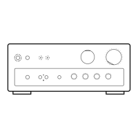
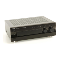
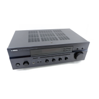
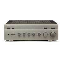
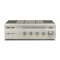
Illustration and labeling of the AX-592 front panel controls.
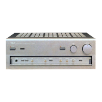
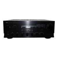
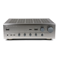
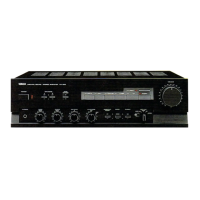
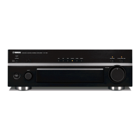
Illustration and labeling of the AX-892 front panel controls.
Diagrams illustrating rear panel connections for AX-592 U, C, R, and A models.
Diagrams illustrating rear panel connections for AX-592 B and G models.
Diagrams illustrating rear panel connections for AX-892 R and G models.
Detailed electrical specifications for the audio amplifier section.
Overall specifications including power supply, consumption, and dimensions.
Physical dimensions of the unit in millimeters and inches.
Diagram showing the internal layout of the AX-592 unit.
Step-by-step instructions for disassembling the AX-592 unit.
Detailed electrical specifications for the audio amplifier section.
Overall specifications including power supply, consumption, and dimensions.
Physical dimensions of the unit in millimeters and inches.
Diagram showing the internal layout of the AX-892 unit.
Step-by-step instructions for disassembling the AX-892 unit.
Procedure to confirm and adjust idling current in the amplifier.
Instructions for safely removing the power transistor.
Pin configuration and data for the μ-COM IC309.
Table mapping selector positions to functions.
Overview of integrated circuits used in the function section.
Waveform examples at specific test points for troubleshooting.
Diagrams showing pin connections for transistors, diodes, and ICs.
Key to symbols used in the main schematic diagram.
Diagrams showing pin connections for transistors, diodes, and ICs.
Overview of integrated circuits used in the function section.
Waveform examples at specific test points for troubleshooting.
Key to symbols used in the main schematic diagram.
Maximum voltage, current, and temperature limits for the IC.
Recommended operating voltage, temperature, and input levels.
Diagram showing the pin layout and numbering for the IC package.
Detailed explanation of each pin's function and properties.
Continued detailed explanation of each pin's function and properties.
Final part of the detailed explanation of each pin's function.
High-level diagram illustrating the internal architecture and data flow of the IC.
Options for configuring the IC's clock oscillator circuit.
Options for selecting a predivider for the oscillator frequency.
Options for setting output levels of ports C and D during reset.
Options for configuring port output types, e.g., open drain or pull-up.
Information on supporting manuals for the IC and development tools.
Details on hardware and software tools for IC development and evaluation.
Description of the EVA-800 system for program development and evaluation.
Maximum voltage, current, and temperature limits for the IC.
Recommended operating voltage, temperature, and input levels.
Detailed electrical parameter values including input/output voltages and currents.
Current drawn with high-level input signals.
Parameters related to the IC's oscillator operation.
Specifics for RC oscillator configuration and frequency.
Diagram showing the typical input waveform for an external clock.
Circuit diagram for using a ceramic resonator as the clock source.
Table detailing selectable combinations of oscillation and predivider options.
Characteristics of RC oscillation for specific configurations.
Maximum voltage, current, and temperature limits for the IC.
Recommended operating voltage, temperature, and input levels.
Detailed electrical parameter values including input/output voltages and currents.
Current drawn with high-level input signals.
Parameters related to the IC's oscillator operation.
Circuit diagram for using a ceramic resonator as the clock source.
Conditions and methods for releasing the IC from HALT (standby) mode.
Important considerations for designing circuits and software using the standby function.
A sample circuit demonstrating power failure backup using the standby function.
Waveforms illustrating the operation during power failure and recovery.
A sample circuit for power failure backup with program selection between reset types.
Waveforms illustrating the operation of Sample Application 2.
A sample circuit for power failure backup that handles instantaneous power breaks.
Waveforms illustrating the operation of Sample Application 3.
Instructions for accessing and manipulating data in memory.
Instructions for operations involving the accumulator register.
Instructions for arithmetic calculations and data comparisons.
Instructions for transferring data between registers and memory.
Instructions for controlling the data pointer register.
Instructions for manipulating working registers.
Instructions for program flow control, including jumps and subroutine calls.
Instructions for setting and clearing status flags.
Instructions for conditional program branching based on flag or data status.
Instructions for interacting with peripheral I/O ports.
Miscellaneous instructions including timer control and halt.
Overview of general purpose NPN silicon transistors.
Physical dimensions of the transistor packages in millimeters.
Key electrical parameters of transistors at 25°C.
Information on packaging types and hFE value classifications.
Graphs illustrating transistor performance characteristics.
High-level functional block diagram of the audio amplifier.
List of electrical components used in the unit.
List of abbreviations used in the parts list.
Component list for the main PCB of the AX-892.
Component list for the function PCB of the AX-892.
Component list for the main PCB of the AX-892.
Component list for the function PCB of the AX-892.
Diagram showing the assembly breakdown of the AX-592 A model.
Diagram showing the assembly breakdown of the AX-592 B model.
Diagram showing the assembly breakdown of the AX-592 G model.
List of parts related to the front panel and escutcheon.
List of Printed Circuit Boards and power transformer parts.
List of various knobs, buttons, and chassis plates.
List of screws, dampers, and other hardware components.
List of accessories, including remote control and battery.
Diagram showing the assembly breakdown of the AX-892 G model.
List of parts for the front panel and escutcheon.
List of PCBs, transformers, and power cord assemblies.
List of knobs, buttons, and chassis-related parts.
List of screws, dampers, and other hardware components.
Circuit diagram of the remote control transmitter.
Table mapping remote control buttons to their corresponding HEX data.
List of carbon resistor values with corresponding part numbers for 1/4W and 1/6W types.
| Type | Integrated Amplifier |
|---|---|
| Input sensitivity | 150mV (line) |
| Frequency response | 20Hz - 20kHz |
| Damping factor | 150 |
| Speaker load impedance | 4Ω to 16Ω |
| Dimensions | 435 x 151 mm |