5
English
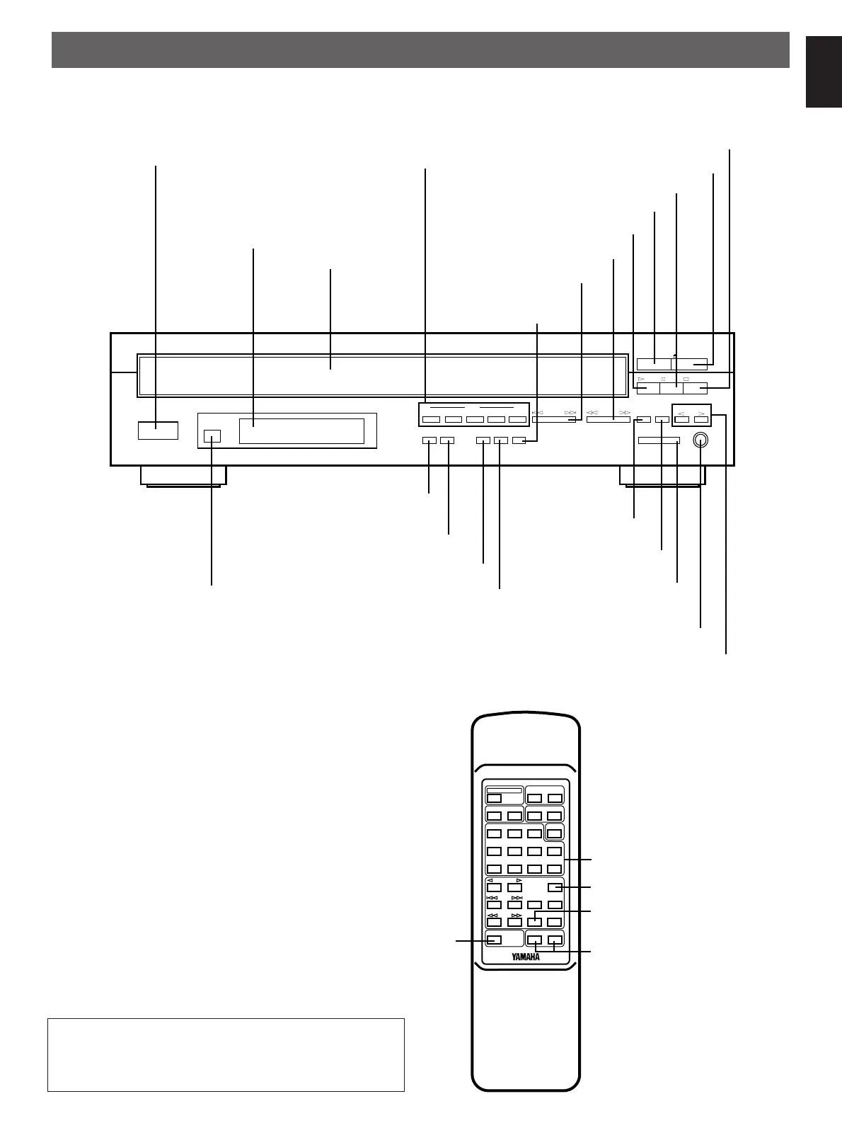
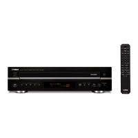
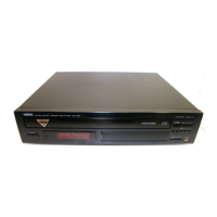
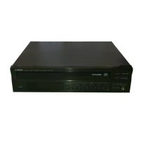
IDENTIFICATION OF COMPONENTS
FRONT PANEL
REMOTE CONTROL TRANSMITTER
The control functions on the main unit and on the remote
control transmitter are virtually identical, with the exceptions
described below.
POWER
Display panel
Remote control sensor (p. 15)
POWER
switch (p. 6)
Disc tray (p. 6)
buttons (p. 6)
DISC SKIP
RANDOM button (p. 10)
PHONES
jack (p. 9)
REPEAT
button (p. 13)
LEVEL
control (p. 9)
OUTPUT
PROG
button (p. 11)
DIMMER button (p. 8)
button (p. 12)
CLEAR
OPEN/CLOSE
button (p. 6)
STOP
button (p. 7)
button (p. 6)
PLAYXCHANGE
button (p. 6)
PLAY
button (p. 7)
PAUSE
SEARCH
button (p. 8)
SKIP
button (p. 7)
select button (p. 6)
MODE
DISC
-select buttons (p. 6)
TIME
1 2345
SKIP
SEARCH
PROG
PLAYXCHANGE
OPEN/CLOSE
PLAY
STOP
DISC SKIP
CLEAR
REPEAT
RANDOM
OUTPUT LEVEL
DOWN UP
PHONES
DISC
MODE
DIMMER
PAUSE
Disc play
TIME
display mode
select button (p. 9)
10
DIMMER
TIME
OPEN/CLOSE
PROG
CLEAR
MODE
123
4
56
7890
+
PLAY
PAUSE
SEARCH
STOP
INDEX
OUTPUT LEVEL
+
–
RANDOM
SKIP
SYNCHRO
REPEAT
DISC SKIP
DISC
SCAN
Numeric buttons (p. 7)
INDEX button (p. 13)
SYNCHRO button (p. 14)
OUTPUT LEVEL buttons (p. 9)
(“+” is identical with “UP”
and “–” with “DOWN” of the
OUTPUT LEVEL control
on the main unit.)
DISC SCAN button (p. 8)
* ( ) indicates the page number on which the control part is best described.
This manual mainly describes how to operate this unit by
using the front panel buttons. To operate this unit on the
remote control transmitter, use buttons with the same name
as those on the front panel.