Do you have a question about the Yamaha CDC-90 and is the answer not in the manual?
Details on replacing components with identical specifications.
Procedure to verify insulation from supply circuits after service.
Safety instructions for servicing laser components.
Warning about lead and other chemicals in product components.
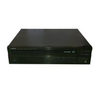
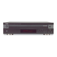
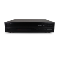
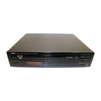
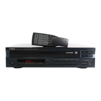
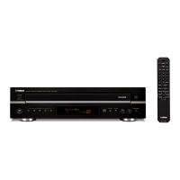
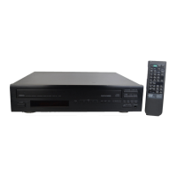
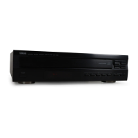
Visual identification of front panel controls and indicators.
Visual identification of front panel controls and indicators.
Visual identification of front panel controls and indicators.
Specific caution for transferring the unit (CDC-625/91 only).
Rear panel view and connections for USA models.
Rear panel view and connections for Canadian models.
Rear panel view and connections for general models.
Rear panel view and connections for European models.
Technical audio performance parameters.
Internal system specifications and components.
General specifications including power and dimensions.
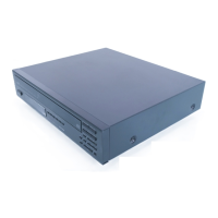
Physical dimensions of the unit with diagrams.
Steps for removing the top cover of the unit.
Steps for installing the top cover.
Steps for removing the shutter assembly.
Steps for removing the tray assembly.
List of measuring instruments required for adjustments.
Tools needed for potentiometer adjustment.
Instructions for test point preparation before adjustment.
Order of adjustments and confirmations.
Procedure to enter TEST mode.
Steps for entering adjustment modes using DISC keys.
Procedure for VCO free run adjustment.
Procedure for focus offset adjustment.
Procedure for tracking offset adjustment.
Procedure to confirm focus search operation.
Procedure to confirm tray loading operation.
Procedure to confirm turntable operation.
Procedure to confirm disc clamper operation.
Procedure to confirm focus and tracking operation.
Procedure for EF balance adjustment.
Procedure to confirm jitter using eye pattern.
Procedure for focus servo gain adjustment.
Procedure for tracking servo gain adjustment.
Procedure to confirm tracking offset.
Procedure to confirm EF balance.
Procedure to confirm focus offset.
Procedure to start the TEST mode.
Explanation of key functions within TEST mode.
Table showing μ-COM operations for each key.
Method to display error messages via remote and main unit.
Table of error codes and their meanings.
Troubleshooting flowcharts for specific error codes.
Troubleshooting for poor table rotation.
Troubleshooting for feed operation defects.
Troubleshooting for focus drops.
Troubleshooting for clamp operation issues.
Diagnosing issues from system malfunctions.
Troubleshooting when unit acts like no disc is present.
Diagnosing issues from system malfunctions.
Troubleshooting for sound skips and display issues.
Troubleshooting for missing search function.
Pin assignments and functions for the System Controller IC.
Pin assignments and functions for the System Controller IC.
Pin assignments and functions for the Signal Processor IC.
Pin assignments and functions for the Signal Processor IC.
Oscilloscope waveform for test point 1.
Oscilloscope waveform for test point 2.
Oscilloscope waveform for test point 3.
Oscilloscope waveform for test point 4.
Mapping semiconductor references to board locations (Parts side).
Mapping semiconductor references to board locations (Foil side).
Schematic for LA9210 RF Amp and Servo Controller.
Schematic for YDC101B Signal Processor & Controller.
Schematic for μPD75216/µPD75P216A System Controller.
Diagrams showing connections for various components.
List of electrical parts, focusing on capacitors.
Continuation of the electrical parts list for capacitors.
List of capacitors, connectors, and diodes.
List of ICs, inductors, connectors, transistors, and resistors.
List of resistors, switches, transformers, and potentiometers.
List of potentiometers, resonators, heatsink, etc.
List of ferrite core, switches, modules, spacers, etc.
List of mechanical parts like panels, motors, screws, and PCB assemblies.
List of mechanical parts for the CM-91 unit.
| Type | CD Player |
|---|---|
| Number of Discs | 5 |
| Frequency Response | 2 Hz - 20 kHz |
| Dynamic Range | 100 dB |
| Channel Separation | 90 dB |
| Output Voltage | 2.0 V |
| Power Consumption | 15 W |
| Disc Format | CD |
| Digital Outputs | Coaxial |