EasyManua.ls Logo

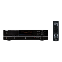
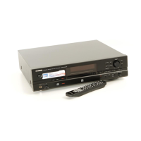
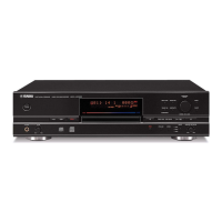
Yamaha CDR-D651 Service Manual

Yamaha CDR-D651
36 pages
To Next Page IconTo Next Page
Page #1 background imageLoading...
Page #1 background image
CDR-D651
SERVICE MANUAL
COMPACT DISC RECORDER
CDR-D651
100732
CONTENTS
TO SERVICE PERSONNEL .......................................... 1
REAR PANELS .............................................................. 3
SPECIFICATIONS.......................................................... 4
INTERNAL VIEW ........................................................... 4
DISASSEMBLY PROCEDURES ............................... 5~6
TEST MODE ............................................................... 7~8
ERROR MESSAGE .................................................. 9~10
µ-COM DATA ......................................................... 11~15
BLOCK DIAGRAM ................................................. 16~17
PRINTED CIRCUIT BOARD .................................. 18~23
SCHEMATIC DIAGRAM ........................................ 24~25
PARTS LIST ........................................................... 26~37
DISPLAY DATA ........................................................... 38
REMOTE CONTROL TRANSMITTER ........................ 39
IMPORTANT NOTICE
This manual has been provided for the use of authorized YAMAHA Retailers and their service personnel.
It has been assumed that basic service procedures inherent to the industry, and more specifically YAMAHA Products, are already
known and understood by the users, and have therefore not been restated.
WARNING: Failure to follow appropriate service and safety procedures when servicing this product may result in personal
injury, destruction of expensive components, and failure of the product to perform as specified. For these reasons,
we advise all YAMAHA product owners that any service required should be performed by an authorized
YAMAHA Retailer or the appointed service representative.
IMPORTANT: The presentation or sale of this manual to any individual or firm does not constitute authorization, certification or
recognition of any applicable technical capabilities, or establish a principle-agent relationship of any form.
The data provided is believed to be accurate and applicable to the unit(s) indicated on the cover. The research, engineering, and
service departments of YAMAHA are continually striving to improve YAMAHA products. Modifications are, therefore, inevitable
and specifications are subject to change without notice or obligation to retrofit. Should any discrepancy appear to exist, please
contact the distributor's Service Division.
WARNING: Static discharges can destroy expensive components. Discharge any static electricity your body may have
accumulated by grounding yourself to the ground buss in the unit (heavy gauge black wires connect to this buss).
IMPORTANT: Turn the unit OFF during disassembly and part replacement. Recheck all work before you apply power to the unit.
CDR-D651
P.O.Box 1, Hamamatsu, Japan
Other manuals for Yamaha CDR-D651

Questions and Answers:

Yamaha CDR-D651 Specifications

General IconGeneral
TypeCD Recorder
Recording MediaCD-R, CD-RW
Frequency Response20 Hz - 20 kHz
Harmonic Distortion0.003%
Digital InputsTOSLINK optical, Coaxial
Analog InputsRCA (L/R)
Digital OutputsTOSLINK optical, Coaxial
Analog OutputsRCA (L/R)
Sampling Frequency44.1 kHz
Bit Depth16-bit
Dimensions435 x 116 x 286 mm
Weight5.5 kg
Supported DiscsCD-R, CD-RW
Total Harmonic Distortion0.003%
Headphone OutputYes
Audio Formats SupportedCD-DA, MP3
Recording FormatsCD-DA

Summary

TO SERVICE PERSONNEL

Critical Components Information

Details about components with special characteristics requiring specific replacement parts.

Leakage Current Measurement

Procedure and limits for verifying insulation and measuring leakage current on 120V models.

CHEMICAL CONTENT NOTICE!

Warning regarding lead in solder and potential chemicals in components.

Laser Safety

Precautions and safety measures for servicing laser components to prevent eye damage.

Laser Emitting conditions

Explains laser beam emission during operation and servicing precautions.

PROTECTION OF EYES FROM LASER BEAM DURING SERVICING

Laser Diode Properties

Lists material, wavelength, emission duration, and laser output for CD and CDR diodes.

REAR PANELS

U, C models

Rear panel layout and connections for U and C model variants.

A model

Rear panel layout and connections for the A model variant.

B, G model

Rear panel layout and connections for B and G model variants.

R model

Rear panel layout and connections for the R model variant.

SPECIFICATIONS

Audio Performance

Technical specifications for audio playback and recording performance.

Laser Diode Properties

Details on laser diode characteristics for CD and CDR drives.

Inputs

Specifications for analog and digital input connections.

Outputs

Specifications for analog and digital output connections, and headphone output.

DIMENSIONS

Physical dimensions of the unit.

INTERNAL VIEW

DISASSEMBLY PROCEDURES

Removal of Top Cover

Step-by-step guide to remove the top cover of the unit.

Removal of Front Panel

Instructions for removing the front panel and disconnecting connectors.

Removal of Tray

Procedure for removing the tray mechanism, applicable to both CD and CD-R drives.

Removal of Pick-up Mechanism on CD drive side

Steps to remove the pick-up mechanism from the CD drive.

Removal of CD Drive Mechanism Unit

Instructions for removing the entire CD drive mechanism unit.

Replacement of CD-R Drive Mechanism Unit Belt

Guide for replacing the drive belt on the CD-R mechanism unit.

Removal of CD-R Drive Mechanism Unit

Steps to remove the CD-R drive mechanism unit from the main chassis.

Installation of Tray

Procedure for installing the tray mechanism, applicable to both drives.

TEST MODE

Starting the Test Mode

How to enter Product Test Mode using the front panel controls.

Changing to the PCB Test Mode (service)

Steps to switch from Product Test Mode to PCB Test Mode via front panel or remote.

PCB Test Mode (service)

Table detailing front panel/remote controller codes for various PCB test functions.

Switching Servo Gain

Explanation of how to adjust servo gain for CD-RW discs in test mode.

Version Check

How to check the software version of the microprocessor and CDR unit.

ERROR MESSAGE

How to have the error message displayed

Procedure to display error messages on the unit's display.

Estimating point of possible cause from error messages

Diagnostic flowcharts to identify causes of common error codes.

Estimating possible cause from erroneous operation

Troubleshooting guides for common operational issues like tray, sound, or disc errors.

μ-COM DATA

Port Pins

Table detailing pin assignments, circuit names, I/O, and functions for the µCOM IC.

IC3: MN35511 Signal Processor & Controller

Pin No. Name I/O Function

Detailed list of pin functions for the MN35511 IC.

BLOCK DIAGRAM

PIN CONNECTION DIAGRAM OF TRANSISTORS, DIODES AND ICS.

Diagrams showing pin connections for various components.

PRINTED CIRCUIT BOARD (Foil side)

MAIN P. C. B.

Foil side layout of the Main Printed Circuit Board with component locations.

Semiconductor Location

Table listing semiconductor component references and their locations on the PCB.

OPE P. C. B. (1)

Foil side layout of the OPE P.C.B. (1) with component locations.

OPE P. C. B. (6)

Foil side layout of the OPE P.C.B. (6) with component locations.

OPE P. C. B. (7)

Foil side layout of the OPE P.C.B. (7) with component locations.

OPE P. C. B. (3)

Foil side layout of the OPE P.C.B. (3) with component locations.

OPE P. C. B. (2)

Foil side layout of the OPE P.C.B. (2) with component locations.

OPE P. C. B. (4)

Foil side layout of the OPE P.C.B. (4) with component locations.

OPE P. C. B. (5)

Foil side layout of the OPE P.C.B. (5) with component locations.

SCHEMATIC DIAGRAM (MAIN)

PIN CONNECTION DIAGRAM OF TRANSISTORS, DIODES AND ICS.

Diagrams showing pin connections for various components.

SCHEMATIC DIAGRAM (OPERATION)

PARTS LIST

ELECTRICAL PARTS

List of electrical components with part numbers, descriptions, and abbreviations.

P. C. B. OPERATION

Parts list specifically for the Operation PCB, including part numbers and descriptions.

P. C. B. OPERATION & P. C. B. MAIN

Parts list for both Operation and Main PCBs, detailing part numbers and descriptions.

P. C. B. MAIN

Parts list specifically for the Main PCB, including part numbers and descriptions.

CHIP RESISTORS

EXPLODED VIEW

R model

Exploded view diagram for the R model, showing component assembly.

MECHANICAL PARTS

List of mechanical parts with part numbers, descriptions, remarks, and market information.

MECHANICAL PARTS

Continues the list of mechanical parts with part numbers, descriptions, remarks, and market information.

ACCESSORIES

List of accessories included with the unit, such as cables and batteries.

EXPLODED VIEW (PU Mechanism Unit / DISC A SIDE)

PU MECHA. UNIT

Exploded view of the PU mechanism unit and its components.

GREASE APPLICATION DIAGRAM (PU Mechanism)

Parts List for Carbon Resistors

DISPLAY DATA

PIN CONNECTION

Pin connection diagram for the display unit.

GRID ASSIGNMENT

Grid assignment mapping for the display segments.

ANODE CONNECTION

Anode connection details for the display unit.

REMOTE CONTROL TRANSMITTER

SCHEMATIC DIAGRAM

Schematic diagram of the remote control transmitter circuit.

KEY NO. FUNCTION CUSTOM DATA CODE

Table mapping remote control keys to functions, custom data, and hex codes.

Related product manuals