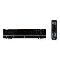
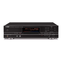
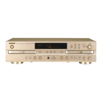
CDR-D651
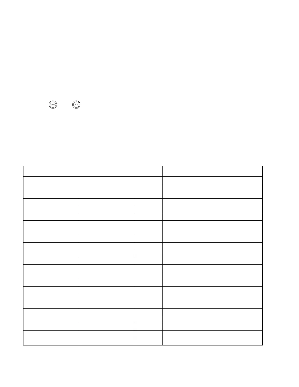
Front panel Remote controller CODE PCB Test Mode (service)
(A) OPEN/CLOSE (A) OPEN/CLOSE 81 (A) Drive open/close
(A) PLAY/PAUSE PLAY 82 (A) Playback if FOCUS ON
(A) STOP STOP 84 (A) All at stop
(A) SKIP - SKIP - 86 (A) FEED shift toward inner track
(A) SKIP + SKIP + 87 (A) FEED shift toward outer track
(B) OPEN/CLOSE (B) OPEN/CLOSE C1
(B) PLAY/PAUSE (A) Spindle acceleration
(B) STOP (A) All at stop
(B) SKIP − MUTE OFF
(B) SKIP + MUTE ON
DISPLAY A
DISPLAY B
TEXT/TIME FL display test
REC REC A0
REC MUTE REC MUTE A1
COPY COPY A3
REC MODE REC MODE A2 Servo gain changed *
1
TRACK No. TRACK No. WRITE A7 Version check *
2
FINALIZE FINALIZE A5 EEPROM test
ERASE ERASE A6 Output changed
INPUT INPUT AB Analog input changed
DISPLAY A/B 9F
TEXT 9D
7
■ TEST MODE
Test Mode
In the test mode, only the CD drive side functions.
There are two test modes. One is Product Test Mode and
the other is PCB Test Mode.
In both modes, the test results can be checked with the
contents displayed on the fluorescent character display
tube. Refer to the separate table for the contents to be
displayed.
Starting the Test Mode
1. In the power off state, press the POWER button while
pressing (
) and ( ) buttons of the DISC A side
of the Front Panel.
2. When the power is turned on and the hand is off from
the button, the mode is set to the Product Test Mode.
At this time, “FQA Mode” appears on the display.
Changing to the PCB Test Mode (service)
Operation on the main unit:
1. In the Product Test Mode, push the MULTI JOG knob.
2. Select the test mode by turning the MULTI JOG knob.
At this time, “PCB Test” appears on the display.
3. Press the MULTI JOB knob to finalize the mode
selection.
Operation on the remote controller:
1. Press the [EDIT] button.
2. Press the [DELETE] button and select the test mode.
At this time, “PCB Test” appears on the display.
3. Press the [SET] button to finalize the mode selection.
After either of the above operations, the mode changes to
the PCB Test Mode.
Use the same procedure to change the mode from the
PCB Test Mode to the Product Test Mode.


 To Next Page