Do you have a question about the Yamaha CX-2000 and is the answer not in the manual?
Information on components requiring specific characteristics for replacement.
Procedure and requirements for verifying insulation and measuring leakage current.
Explanation of the polarized AC line plug safety feature for U.C. models.
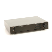
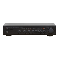
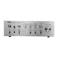
Diagrams and layout of the front panels for CX-1000U, U, C, and G models.
Diagrams and layout of the front panels for CX-1000 A, B, and R models.
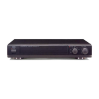
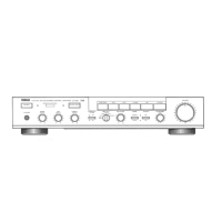
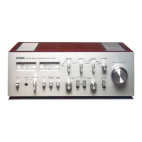
Diagram and layout of the CX-2000 front panel.
Diagrams of the RS-CX1000 and RS-CX2000 remote control units.
Diagram of the rear panel for CX-1000/U U and C models.
Diagram of the rear panel for CX-1000/U A model.
Diagram of the rear panel for CX-1000/U B model.
Diagram of the rear panel for CX-1000/U G model.
Diagram of the rear panel for CX-1000/U R model.
Covers input sensitivity, max input signal, output level, frequency response, RIAA, THD, IMD, S/N.
Details on tone controls, filter characteristics, and continuous loudness control.
Information on power supply, consumption, AC outlet, physical dimensions, and unit weight.
Diagrams identifying the power transformer and various circuit boards.
Layouts showing the placement of digital and analog processing circuitry.
Diagrams showing the physical dimensions of the CX-1000/U unit.
Diagrams showing the physical dimensions of the CX-2000 unit.
Step-by-step instructions for removing the bottom and top covers.
Instructions for removing the front panel and shield plate.
Steps for removing the bottom cover, top panels, and front panel.
Instructions for removing the shield plate and side panels.
Procedure for adjusting the distortion degree of the amplifier circuit.
Procedure for adjusting the offset of the amplifier part.
Procedure for adjusting the output level of the D/A converter.
Block diagram and pinout for the IC433 microcomputer (LC6554H-3709).
Diagrams for PCM56P-K D/A converters and NJM5532 dual op-amps.
Diagrams for AN7812/AN7912 regulators and μPD74HC238C decoder.
Diagrams for NJM78M12A regulators and TC74HC08 logic gates.
Diagrams for LB1294 LED driver and YM3023 sample hold ICs.
Diagrams for μPD74HC151C data selectors and YM3414 digital filters.
Diagrams for μPD74HCU04C inverters, μPD74HC123AC single shots, and NAND/NOR gates.
Diagrams for YM6013 over sampling and NJM7805A regulator ICs.
Diagram and explanation of YM3623B digital I/O functions and pin assignments.
Diagrams for μPD74HC157C multiplexer and BA6209 motor driver ICs.
Diagrams for LA7952 video switch, NJM5532DD op-amp, and U701 remote control ICs.
High-level block diagram showing signal flow and control logic.
Blocks related to digital processing, power supply, and output stages.
Layout diagrams for Equalizer Circuit Boards (1) and (3).
Layout diagrams for Equalizer Circuit Boards (4) through (12).
Layout diagrams for Digital Circuit Boards (2), (3), and (4).
Layout diagrams for Equalizer Circuit Boards (2) and (9) through (12).
Layout diagrams for Digital Circuit Boards (3) and (4).
Layout diagram for DIGITAL Circuit Board (1) pattern and component sides.
Layout diagram for DIGITAL Circuit Board (2).
Layout diagram for ANALOG Circuit Board (2).
Layout diagram for ANALOG Circuit Board (1) pattern side.
List of components used in the schematic diagram with references.
Schematic detailing signal paths and component locations.
Guide for identifying various electronic components used in the unit.
Diagrams showing wiring between digital, analog, and equalizer boards.
Wiring diagrams illustrating connections between equalizer boards.
List of electrical components with part numbers and descriptions.
List of transistors, diodes, and integrated circuits with part numbers.
List of connectors, jacks, and other miscellaneous components.
List of ceramic caps, electrolytic caps, coils, and resonators.
List of potentiometers, heat sinks, and other components.
List of ICs, diodes, transistors, and switches with part numbers.
List of transmission modules, switches, terminals, and connectors.
List of equalizer circuit boards and various types of capacitors.
List of coils, electrolytic capacitors, and ceramic capacitors.
List of transformers, fuses, relays, and various resistors.
List of LEDs, switches, transistors, diodes, and ICs.
Exploded view of the main chassis and panel components.
Identification of internal mechanism parts in the exploded view.
List of mechanism parts including panels, frames, and dampers.
List of electronic components, screws, and rivets for the mechanism.
List of circuit boards, cord stoppers, and power cords for the mechanism.
List of mechanism parts including transformers, switches, and LEDs.
List of mechanism transistors, ICs, and connectors.
Schematic diagram for the RS-CX1000/2000 remote control transmitter.
Printed circuit board layout for the remote control transmitter.
Exploded view of the remote control transmitter's housing and components.
List of carbon resistors by value, including 1/4W and 1/6W part numbers.
| Type | Preamplifier |
|---|---|
| Input Sensitivity | 150 mV |
| Total Harmonic Distortion (THD) | 0.003% |
| Input Impedance | 47kOhms (line) |
| Channel separation | 80dB (20Hz - 20kHz) |