Do you have a question about the Yamaha CA-610 and is the answer not in the manual?
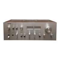
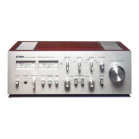
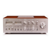
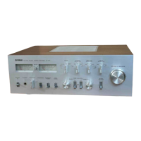
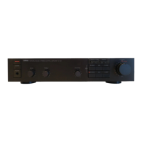
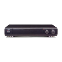
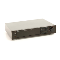
Overview and identification of front panel controls and indicators.
Identification of rear panel connections for general models.
Identification of rear panel connections for European models.
Details on dynamic, RMS, and bandwidth power outputs.
Specifications for harmonic, intermodulation distortion, and residual noise.
Specifications for frequency response and damping factor.
Specifications for input sensitivity, impedance, and output levels.
Specifications for tone controls, filters, and loudness.
Specification for signal-to-noise ratio.
Specifications for auxiliary circuits, semiconductors, power, and dimensions.
Illustration of internal components from the top perspective.
Illustration of internal components from the bottom perspective.
Step-by-step instructions for removing the top cover.
Step-by-step instructions for removing the bottom panel.
Step-by-step instructions for removing the front panel.
Diagram illustrating the audio signal path and component interconnections.
General precautions and preparation steps before performing adjustments.
Procedure for adjusting the idling current.
Procedure to check and verify zero potential points.
Schematic diagram of the equalizer circuit board.
Instructions for voltage conversion for US and Canadian models.
Instructions for voltage conversion for European and British models.
Instructions for voltage conversion for Australian models.
Detailed schematic of the main circuit board.
Diagram illustrating the unit packaging process.
Illustration showing numbered parts for identification.
| Signal to Noise Ratio | 80dB (MM), 90dB (line) |
|---|---|
| Type | Stereo Integrated Amplifier |
| Year | 1977 |
| Input Sensitivity | 2.5mV (MM), 150mV (line) |
| Speaker Load Impedance | 4Ω to 16Ω |