Do you have a question about the Yamaha DA824 and is the answer not in the manual?
Precautions for rack installation including ventilation clearance and spacing from heat sources.
Critical warnings covering environmental hazards, electrical safety, cord handling, and product care.
Guidelines for environmental conditions, condensation, and handling potential noise from wordclock changes.
Steps for connecting the power cord and turning the DA824 on/off safely.
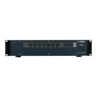
Explanation of all ports, connectors, and switches found on the rear panel of the DA824.
Step-by-step guide on how to install optional mini YGDAI cards into the DA824.
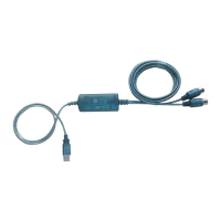
Illustrates connecting the DA824 to devices via AES/EBU using the MY8-AE card.
Illustrates connecting the DA824 to devices via ADAT using the MY8-AT card.
The Yamaha DA824 is a high-performance 8-channel digital-to-analog converter designed for professional audio applications. It features 24-bit linear digital-to-analog converters and 128-times oversampling, providing a wide dynamic range for accurate audio reproduction.
The primary function of the DA824 is to convert digital audio signals into analog audio signals. It supports various popular digital audio interconnect formats through optional mini YGDAI (Yamaha General Digital Audio Interface) cards. These cards allow the DA824 to interface with different digital audio devices, including those using AES/EBU, ADAT, and Tascam TDIF-1 formats.
The DA824 is equipped with eight analog outputs, each featuring its own output-level switch for presetting the maximum output level. These settings can be adjusted to +24 dB, +18 dB, +15 dB, and +4 dBV, offering flexibility to match different analog equipment requirements.
For synchronization, the DA824 relies on a wordclock signal. It can lock to a wordclock signal derived from its SLOT digital audio inputs or from an external wordclock source connected to the WORD CLOCK IN connector. A LOCK indicator on the front panel visually confirms whether the DA824 is synchronized to the wordclock source.
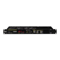
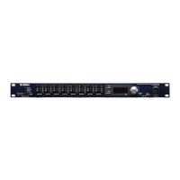
The front panel of the DA824 provides clear visual feedback on signal levels and synchronization status.
The DA824 features a recessed [POWER] switch on the front panel to prevent accidental operation. It's crucial to follow a specific power-on and power-off sequence for your audio equipment to prevent audible thumps and clicks. When powering on, sound sources, mixers, or recorders should be turned on first, followed by the DA824, and then power amplifiers. When powering off, this order should be reversed.
The rear panel offers a comprehensive set of connectors for integration into a professional audio system.
The DA824's flexibility is greatly enhanced by its support for optional mini YGDAI cards. These cards allow the unit to adapt to different digital audio environments.
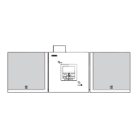
Proper wordclock synchronization is critical for correct digital-to-analog processing. The DA824 can derive its wordclock from its digital audio inputs or an external BNC wordclock source. The manual provides examples of wordclock hookups, including scenarios where the DA824 sources wordclock from its SLOT digital audio inputs or from the WORD CLOCK IN connector. It also details different wordclock distribution methods (distribution box, bus, and daisy chain) and how to apply termination correctly using the WORD CLOCK 75Ω ON/OFF switch.
The DA824 can be used freestanding or rack-mounted. For proper ventilation, it's crucial to leave adequate free space around the unit: 10 cm at the sides, 15 cm behind, and 30 cm above. When rack-mounting, especially in a portable rack case, the rear of the rack should be open to ensure airflow. Avoid mounting the DA824 next to heat-generating equipment like power amplifiers to prevent overheating, which could lead to damage or fire.
The device should be operated in an environment where the temperature is between 10°C and 35°C (50°F and 95°F). It should not be exposed to extreme temperatures, humidity, direct sunlight, or dust. If the unit is moved from a cold to a warmer environment, or if the temperature rises sharply, condensation may form inside. In such cases, allow the DA824 to acclimatize for about an hour before use to prevent performance issues.
To clean the DA824, use only a soft, dry cloth. Do not use benzene, thinner, cleaning detergent, or chemical cloths, as these can damage the unit's finish.
Always hold the power-cord plug when disconnecting it from an AC outlet; never pull the cord itself, as this can damage the cord and create a fire or electrical shock hazard. Avoid placing heavy objects on the power cord, scratching, bending, twisting, pulling, or heating it. If the power cord is damaged, it should be replaced by a dealer.
The DA824 uses high-frequency digital circuits that may cause interference with nearby radio and television equipment. If interference occurs, relocating the affected equipment may resolve the issue.
When installing mini YGDAI cards, first turn off the DA824. Undo the two fixing screws and remove the slot cover, keeping the cover and screws in a safe place. Insert the card between the guide rails and slide it firmly into the slot until it plugs into the DA824 connector. Finally, secure the card using the attached thumbscrews, ensuring they are tight for proper grounding.
When changing the wordclock source, especially if an MY8-AT I/O card is installed, the DA824's analog outputs may produce noise. To prevent this, turn down your power amplifiers beforehand. Similarly, when changing the wordclock source on the wordclock master device (e.g., AD824 or DME32), turn down your power amplifiers or turn off the DA824.
| Model | DA824 |
|---|---|
| Manufacturer | Yamaha |
| Input Channels | 8 |
| Output Channels | 8 |
| Bit Depth | 24-bit |
| Dynamic Range | 110 dB |
| Sampling Frequency | 44.1 kHz, 48 kHz |
| Digital Audio Interface | AES/EBU |
| Analog Audio Interface | XLR |
| Power Supply | AC 100V, 50/60Hz |
| Dimensions | 480 x 44 mm |