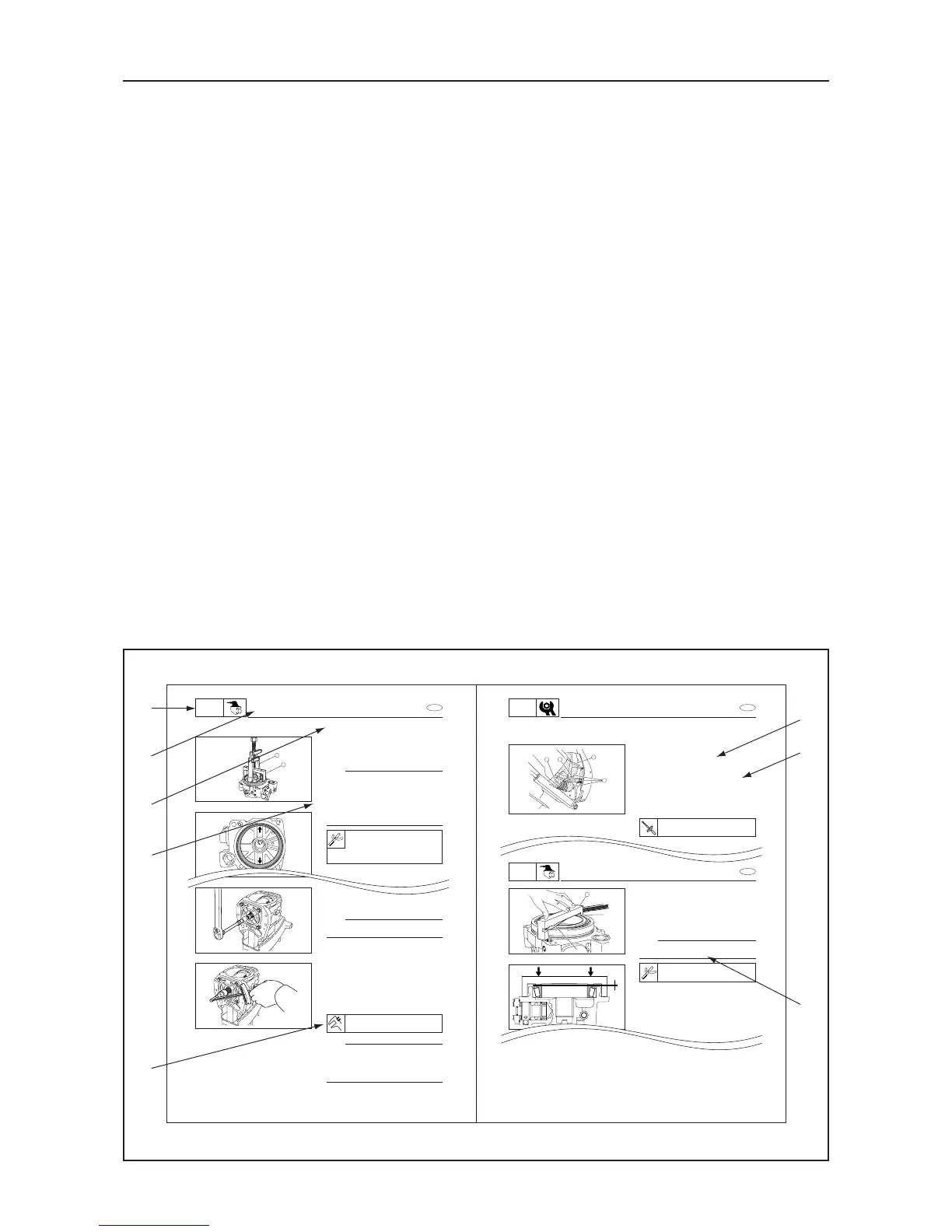
CONSTRUCTION OF THIS MANUAL
This manual consists of chapters for the main categories of subjects. (See “Symbols” on the
next page.)
1st title 1 : This is a chapter with its symbol on the upper right of each page.
2nd title 2 : This title appears on the top of the each page, to the left of the chapter symbol.
3rd title 3 : This title precedes the paragraphs describing the working procedure.
All the procedures in this manual are organized in a sequential, step-by-step order. The infor-
mation has been compiled to provide the mechanic with an easy-to-read, handy reference that
contains comprehensive explanations of all disassembly, check, repair, and assembly proce-
dures.
Important procedures including removing, checking, and assembling steps 4 are explained in
detail.
IMPORTANT FEATURES
¡ Important engine data and information about special tools framed in a box together with
an illustrative symbol 5.
¡ A circled numeral 6 indicates a part name. A circled lower case letter indicates data or an
alignment mark 7.
¡ An arrow 8 indicates the course of action required to remedy the started condition of a
component.
EXPLODED DIAGRAM
Each chapter begins with exploded diagrams which facilitate correct disassembly and assem-
bly.
SHIM SELECTION (UPPER UNIT HOUSING)
R-gear Shim (T5) Adjustment
1. Use the guide, bearing puller 2 1 and
the bearing puller 2 to remove the bear-
ing outer race from the selector valve
housing.
NOTE:
¡ When the bearing and the selector valve
housing are not replaced, DO NOT re-
move the bearing outer race.
¡ When replacing the bearing, replace the
total inner and outer set.
¡ Make sure that the bearing puller is set at
the position specified in the illustration.
Guide, bearing puller 2:
6U4-30-3
Bearing puller:
6U4-35
1
2
E
UPPER
UNIT
Drive shaft motive torque (A):
0.4 – 1.5 N·m
3. Loosen the front bearing housing bolts
to 1/2 rotation and measure pre-load B
(motive torque) of the drive shaft.
NOTE:
Measure resistance of the clutch disk section
as the pre-load B (motive torque).
4. Calculate the drive shaft pre-load (mo-
tive torque) based on the pre-load (mo-
tive torque) A and B.
Formula:
Drive shaft pre-load = pre-load (A) – pre-
load (B)
NOTE:
If the drive shaft pre-load (motive torque) is
greater than the specification, reduce the
shim T6b. If the drive shaft pre-load (motive
torque) is less than the specification, increase
the shim T6b.
4-27
T
.
R
Clamp screw:
3 N·m
BELLOWS AND HOSE INSPEC-
TION
1. Inspect:
¡ Shift cable bellows 1
¡ Exhaust bellows 2
¡ Universal joint bellows 3
Cracks/Weathering/Damage → Re-
place.
Loose clamps 4 → Tighten.
Refer to “SWIVEL BRACKET AND
BELLOWS” section (P7-7).
3
12
4
E
INSP
ADJ
BELLOWS AND HOSE INSPECTION
UPPER UNIT HOUSING
3. After inserting the bearing outer race
with press, install the inner race. Use the
shimming tool, T5/T6a 1 to measure the
clearance (Measurement B) between the
tool and the bearing with a thickness
gauge.
NOTE:
To h av e th e cl ea ra nc e, m e as ur e th e li ne b e-
tween the point A and B on the bearing.
4. Find the stamped R-valve of the upper
gear case.
Shimming tool, T5/T6a:
6U4-28
A
B
1
B
E
UPPER
UNIT
1
6
8
7
2
3
4
5
⎧
⎪
⎪
⎪
⎨
⎪
⎪
⎪
⎩