DU1A
15
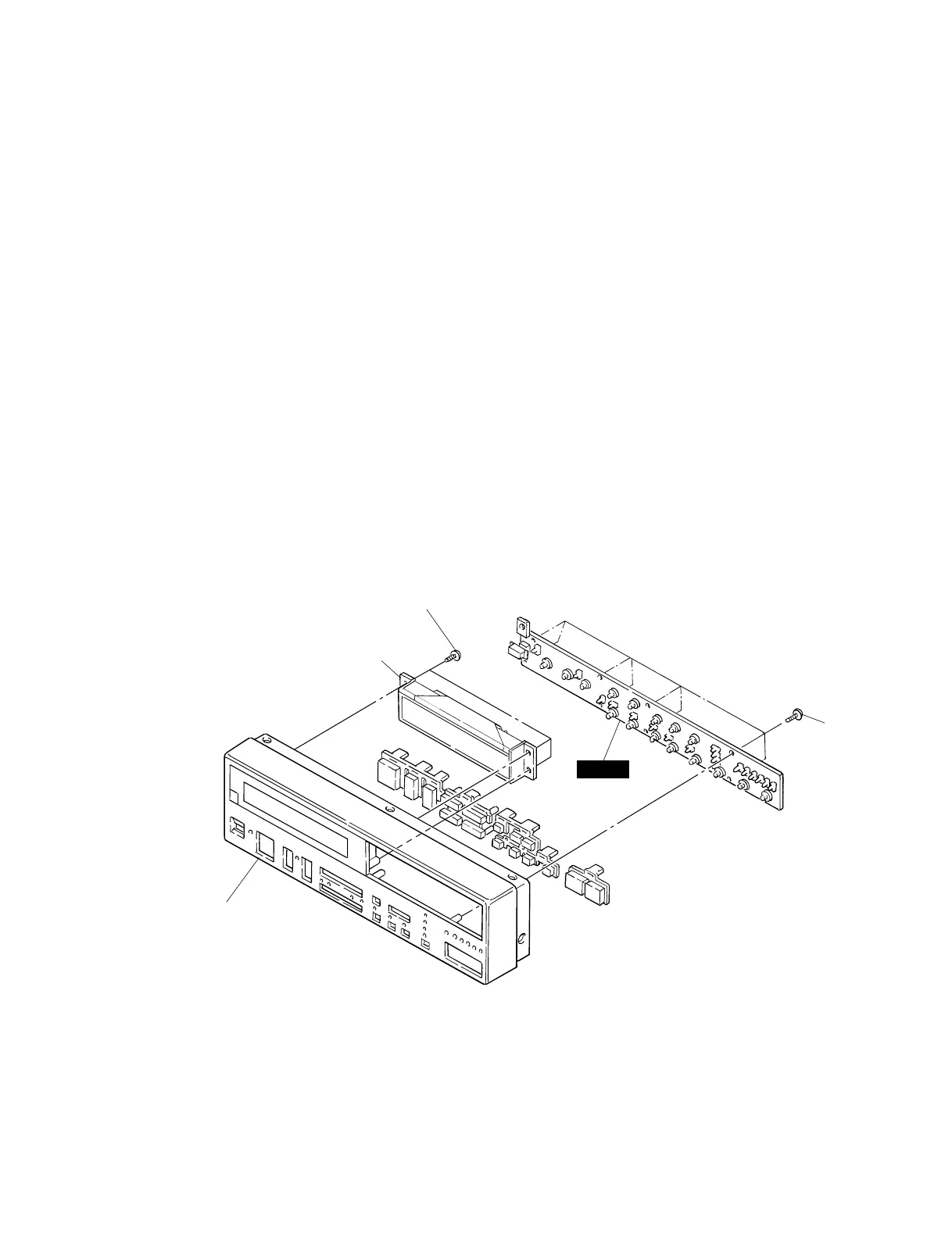
7. Panel Unit CD (Time required: About 5 minutes)
7-1 Remove the top cover CD. (See procedure B-1.)
7-2 Remove the panel. (See procedure B-5.)
7-3 Remove the five (5) screws marked [21GA]. The panel
unit CD can then be removed. (Fig.1)
8. PASW Circuit Board
(Time required: About 7 minutes)
8-1 Remove the top cover CD. (See procedure B-1.)
8-2 Remove the panel unit CD. (See procedure B-7.)
8-3 Remove the eight (8) screws marked [61GB]. The PASW
circuit board can then be removed. (Fig.2)
9. LCD Assembly
(Time required: About 6 minutes)
9-1 Remove the top cover CD. (See procedure B-1.)
9-2 Remove the panel unit CD. (See procedure B-7.)
9-3 Remove the three (3) screws marked [51GA]. The LCD
assembly can then be removed. (Fig.2)
10. FDD Unit
(Time required: About 6 minutes)
10-1 Remove the top cover CD. (See procedure B-1.)
10-2 Remove the panel unit CD. (See procedure B-7.)
10-3 Remove the three (3) screws marked [43G]. The FDD
unit can then be removed. (Fig.1, Photo.2)
11. CONTROLLER (CTRL) Circuit Board
(Time required: About 8 minutes)
11-1 Remove the top cover CD. (See procedure B-1.)
11-2 Remove the panel unit CD. (See procedure B-7.)
11-3 Remove the FDD unit. (See procedure B-10.)
11-4 Remove the screw marked [61GA], the three (3) screws
marked [71G], the two (2) screws marked [72G], the two
(2) lock screws marked [73G] and the screw marked
[74G]. The CONTROLLER (CTRL) circuit board can then
be removed. (Fig.1, Photo.2,3)
12. Sounder Assembly
(Time required: About 9 minutes)
12-1 Remove the top cover CD. (See procedure B-1.)
12-2 Remove the panel unit CD. (See procedure B-7.)
12-3 Remove the FDD unit. (See procedure B-10.)
12-4 Remove the sounder assembly, which is attached to the
bottom chassis with adhesive tape. (Fig.1)
[61GB]
[51GA]
LCD assembly
PASW
Panel unit CD
(Fig.2)
[51GA]: Bind Head Tapping Screw-P 2.6X8 MFZN2BL (EP620120)
[61GB]: Bind Head Tapping Screw-P 2.6X8 MFZN2BL (EP620120)
 Loading...