DU1A
22
[071S]x4
[071S]
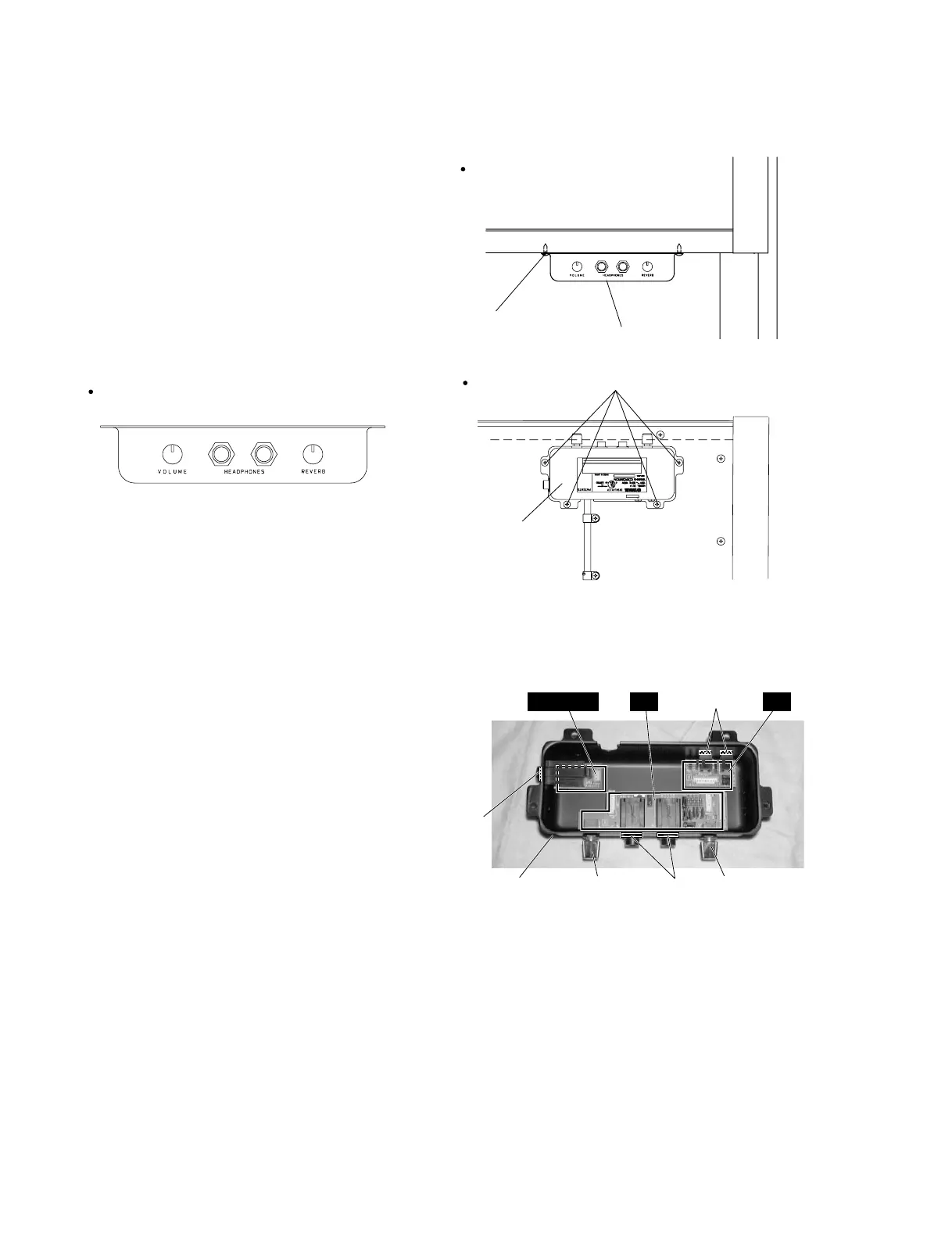
Switch box unit
Switch box unit
VOLUME knobSwitch box unit
[I]
[21GB]
REVERB knob
[H]
CTRL IN U HP (1/2) HP (2/2)
(Photo.16)
[21GB]:Hexagonal Nut 12.0X14X2 MFZN2BL (VB508600)
(Fig.12)
[071S]: Truss Head Tapping Screw-1 4.0X12 MFZN2BL (03747270)
Bottom view
Front view
Front view
20. Switch Box Unit
(Time required: About 1 minute)
20-1 Remove the four (4) screws marked [071S]. The switch
box unit can then be removed. (Fig.12)
21. HP (1/2) Circuit Board (Time required: About 5 minutes)
21-1 Remove the switch box unit. (See procedure B-20.)
21-2 Remove the VOLUME and REVERB knobs, and remove
the two (2) hexagonal nuts marked [21GB]. The HP (1/2)
circuit board can then be removed. (Photo.16)
22. HP (2/2) Circuit Board
(Time required: About 4 minutes)
22-1 Remove the switch box unit. (See procedure B-20.)
22-2 Remove the two (2) hexagonal nuts marked [H]. The HP
(2/2) circuit board can then be removed. (Photo.16)
23. CTRL IN U Circuit Board
(Time required: About 4 minutes)
23-1 Remove the switch box unit. (See procedure B-20.)
23-2 Remove the hexagonal nut marked [I]. The CTRL IN U
circuit board can then be removed. (Photo.16)
 Loading...