RX-V2400/RX-V2400RDS/DSP-AX2400
RX-V1400/RX-V1400RDS/HTR-5690/DSP-AX1400
19
RX-V2400/RX-V2400RDS/DSP-AX2400
RX-V1400/RX-V1400RDS/HTR-5690/DSP-AX1400
■ DISASSEMBLY PROCEDURE/分解手順
1. トップカバーの外し方
2. フロントパネルの外し方
* The description below uses RX-V2400RDS (G model)
as a representative model.
(Remove parts in the order as numbered.)
Disconnect the power cable from the AC outlet.
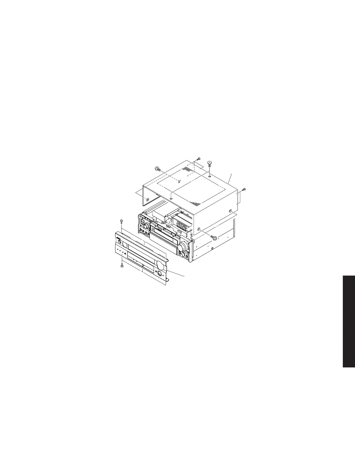
1. Removal of Top Cover
a. Remove 2 screws (1), 4 screws (2) and 5 screws (3).
(Fig. 1)
b. Slide the Top Cover rearward to remove it. (Fig. 1)
2. Removal of Front Panel
Remove 6 screws (4) and then remove the Front Panel
forward. (Fig. 1)
Fig. 1
Top Cover
Front Panel
1
2
2
3
3
4
4
3. Removal of Sub Chassis
a. Remove 4 push rivets (5) and then remove the Side
Plates. (Fig. 2)
b. Remove 2 screws (6) and 2 screws (7). (Fig. 2)
c. Remove CB25, CB509, CB512, CB861 ~ CB864. (Fig.
3)
d. Remove the Sub Chassis forward. (Fig. 2)
4. Removal of DSP P.C.B.
a. Remove 2 screws (8) and then remove the Supports.
(Fig. 2)
b. Remove 5 screws (9) and then remove the Bracket.
(Fig. 2)
c. Remove 3 screws (0). (Fig. 2)
d. Remove 8 screws (A). (Fig. 4)
e. Remove CB501, CB503 ~ CB505. (Fig. 3)
f. Remove the DSP P.C.B. upward. (Fig. 2)
5. Removal of VIDEO (2) P.C.B.
a. Remove 1 screw (B). (Fig. 2)
3. サブシャーシの外し方
4. DSPP.C.B.の外し方
5. VIDEO(2)P.C.B.の外し方
 Loading...

