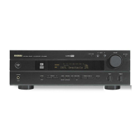
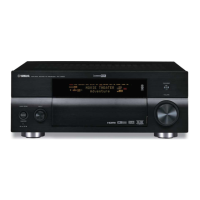
Do you have a question about the Yamaha DSP-AX530 and is the answer not in the manual?
Physical dimensions of the unit in millimeters and inches.
The weight of the unit in kilograms and pounds.
Details on the available finish colors and model variations.
List of items included in the package with the unit.
Table detailing set menu options, preset values, and setting ranges for various functions.
Table showing the adjustable ranges and steps for various operational parameters.
Procedure for replacing the power transistor and speaker protective relay.
Instructions on how to initiate the diagnostic mode using specific button presses on the main unit.
Method to start DIAG mode with protection functions disabled for troubleshooting.
How the FL display indicates the unit's status, version, and DIAG menu during operation.
Display information shown when no protection function history is recorded.
Display information shown when protection function history is recorded.
Information displayed on the FL indicator during diagnostic menu operations.
How to navigate and operate the diagnostic menus and sub-menus using unit or remote keys.
How protection function history is stored, cleared, and its implications for service.
Additional functions available during DIAG mode, beyond standard menu operations.
Default settings applied when entering the DIAG mode and how they are restored upon exit.
In-depth explanation of specific DIAG menu items, including signal output details and reference data.
Details on the DSP THROUGH function, including signal path and output levels.
Details on the YSS FULL BIT function and its signal output characteristics.
Details on the YSS FULL BIT F function and its signal output characteristics.
Explanation of the RAM THROUGH function for YSS938, focusing on CT signal output.
Explanation of PRO LOGIC processing, including signal routing and sub-menu selections.
Explanation of speaker settings, including input signal identification and analog switch settings.
Details on the MARGIN CHECK function, focusing on signal output with head margin.
Explanation of the OTHER INPUT function, specifically the 6CH input signal output.
Procedure for checking the FL display section, including segment and driver functionality tests.
How to use the DSP's built-in noise generator for testing various channels and frequencies.
How to protect user memory or reset settings to factory defaults via the FACTORY PRESET menu.
Using sub-menus to check A/D conversion values of panel keys and protection functions, and FAN TEST.
Information on power supply voltage protection values and how they trigger protection.
How panel key A/D values deviate from standard values, requiring checks on resistors and solder.
Detection of speaker impedance and power limiter status via input voltage of IC301 pin 95.
Monitoring temperature detection values and fan drive levels for operational status.
Displays status information of the microprocessor and input signals in hexadecimal notation.
Self-diagnosis of bus connections for YSS938 and external RAM.
Switching PCB function settings via software for product operation and protection function control.
Displays microprocessor version, checksum, and port settings, including AAC function detection port state.
Instructions to confirm and adjust idling current by measuring voltage across specific points on the MAIN (1) PCB.
Diagrams showing pin connections for various ICs and semiconductor components.
Diagrams illustrating grid assignments for the display elements, showing anode and grid connections.
Table detailing anode connections for various display segments across different models.
Pin connection diagrams for integrated circuits (ICs) used in the unit.
Pinout diagrams for various diode types used in the unit.
Pinout diagrams for various transistor types used in the unit.
Warning regarding replacement of special characteristic components and use of correct parts.
List of abbreviations used in the parts list for component identification.
List of electrical components, including capacitors, resistors, connectors, and ICs.
List of parts categorized by the PCB they are mounted on, detailing their function and market applicability.
Parts list entries related to PCB operation and DSP functions, categorized by part type.
Parts list entries specific to the video processing PCBs.
Parts list entries for components mounted on the main PCBs, including transistors, resistors, and connectors.
List of chip resistors with their part numbers, values, and specifications.
List of mechanical parts, including panels, screws, buttons, and chassis components.
List of accessories provided with the unit, such as remote controls, antennas, and cables.
Key number mapping for the remote control schematic, linking button functions to default codes and schematic references.


 Loading...