ABCDEFGH I JKL
RX-V530/RX-V530RDS/HTR-5550/HTR-5550RDS/DSP-AX530
RX-V430/RX-V430RDS/HTR-5540/HTR-5540RDS/DSP-AX430
71
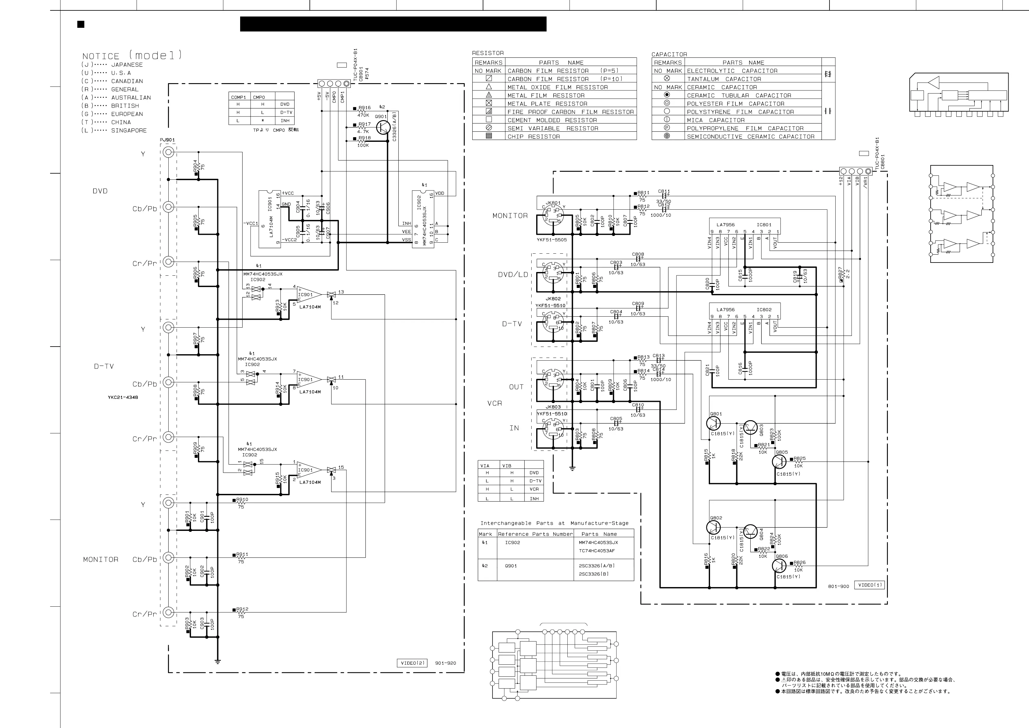
SCHEMATIC DIAGRAM (VIDEO) RX-V530/RX-V530RDS/HTR-5550/HTR-5550RDS/DSP-AX530 only
1
2
3
4
5
6
7
8
9
★ All voltages are measured with a 10MΩ/V DC electric volt meter.
★ Components having special characteristics are marked s and must be replaced
with parts having specifications equal to those originally installed.
★ Schematic diagram is subject to change without notice.
C-INPUT SELECTOR
Y-INPUT SELECTOR
Y SELECTOR
Cb SELECTOR
Cr SELECTOR
IC801, 802: LA7956
Video Switch
123456789
VIDEO
OUT
A B VIN1 GND VIN2 VCC VIN3 VIN4
DRIVER
6dB
AMP
CONTROL
4 INPUT 1 OUTPUT
VIDEO SWITCH
IC901: LA7104M
Video Amp
15
VOUT1
13
VOUT2
11
VOUT3
10
MUTE2
9
-VCC2
12
DR CTL
16
+VCC
14
GND
2
NFB1
4
VIN2+
6
-VCC1
7
VIN3+
8
NFB3
5
NFB2
1
VIN1+
3
MUTE1
DR6dB
DR6dB
DR6dB
IC902: MM74HC4053SJX
Triple 2-Channel Analog Multiplexer
16
11
10
4
7
OUT/IN
AX or AY
VSS
8
GND
C
B
A
VCC
3
CY
5
CX
1
BY
2
BX
IN/OUT
13
AY
12
AX
TO
Logic
Level
Conversion
Logic
Level
Conversion
Logic
Level
Conversion
OUT/IN
CX or CY
OUT/IN
BX or BY
9INH
Logic
Level
Conversion
Binary to 1
of 2 Decoders
with INHBIT
Binary to 1
of 2 Decoders
with INHBIT
Binary to 1
of 2 Decoders
with INHBIT
YG
TG
TB
TC
TG
Page 68
to FUNCTION (4)
A4
Page 68
to FUNCTION (4)
A2
7.4
6.4
6.47.0 7.0
11.9
6.4
0
11.9
7.4
7.0
6.56.4 6.4
11.9
3.9
3.9
11.9
3.9
0
3.9
4.9
4.9
6.4
3.9
5.05.0
-5.0
0
0
0
0
0
5.0
-5.0
0
0
0.7
0
0
0
0
0
-5.0
0
3.9
11.9
3.9
0
3.9
4.9
4.9
6.5
5.7
0
11.9
0
0
0
0
0
0
5.0
0
0
0
0
0
0
5.0
0
 Loading...